
Lithium-ion secondary battery and method of manufacturing the same

a secondary battery and lithium-ion technology, applied in the direction of cell components, final product manufacturing, sustainable manufacturing/processing, etc., can solve the problems of capacity deterioration, increase in resistance, capacity deterioration, etc., and achieve high output, reduce the effect of phosphate film resistance and compatibly suppressed resistan

Inactive Publication Date: 2016-03-17
TOYOTA JIDOSHA KK
View PDF3 Cites 0 Cited by
  • Summary
  • Abstract
  • Description
  • Claims
  • Application Information

AI Technical Summary

Benefits of technology

The present invention relates to a lithium-ion secondary battery having a high output and good cycle characteristics. The technical effect is achieved by using an inorganic phosphate compound as an acid consuming material that stably functions at the open voltage of the battery. This prevents capacity deterioration and an increase in resistance caused by transition metal elution from the positive active material and phosphate films. The use of a spinel positive active material with high thermostability and electrical conductivity also enhances battery performance and durability. Additionally, optimizing the content of the inorganic phosphate compound with respect to the surface area of the positive active material prevents excessive capacity deterioration and an increase in resistance.

Problems solved by technology

The generated acid becomes a cause of the elution of transition metal components in the positive active material, and there is concern that capacity deterioration may occur.
However, when the content of the inorganic phosphate compound is too high, the influence of phosphate films is increased, and this may cause an increase in resistance.
In accordance with this, capacity deterioration occurs.

Method used


Image

  • Lithium-ion secondary battery and method of manufacturing
the same
  • Lithium-ion secondary battery and method of manufacturing
the same
  • Lithium-ion secondary battery and method of manufacturing
the same

Examples


Embodiment Construction

[0033]Hereinafter, embodiments of the present invention will be described. Items which are not items that are particularly mentioned in the specification and are necessary items for the implementation of the present invention can be recognized as design items by those skilled in the related art in the corresponding field. The present invention can be implemented on the basis of the contents disclosed in the specification and general technical knowledge in the corresponding field. In the following drawings, like members and sites having the same actions are denoted by like reference numerals, and an overlapping description may be omitted or simplified. In each of the drawings, the dimensional relationships (length, width, thickness, and the like) do not necessarily reflect actual dimensional relationships.

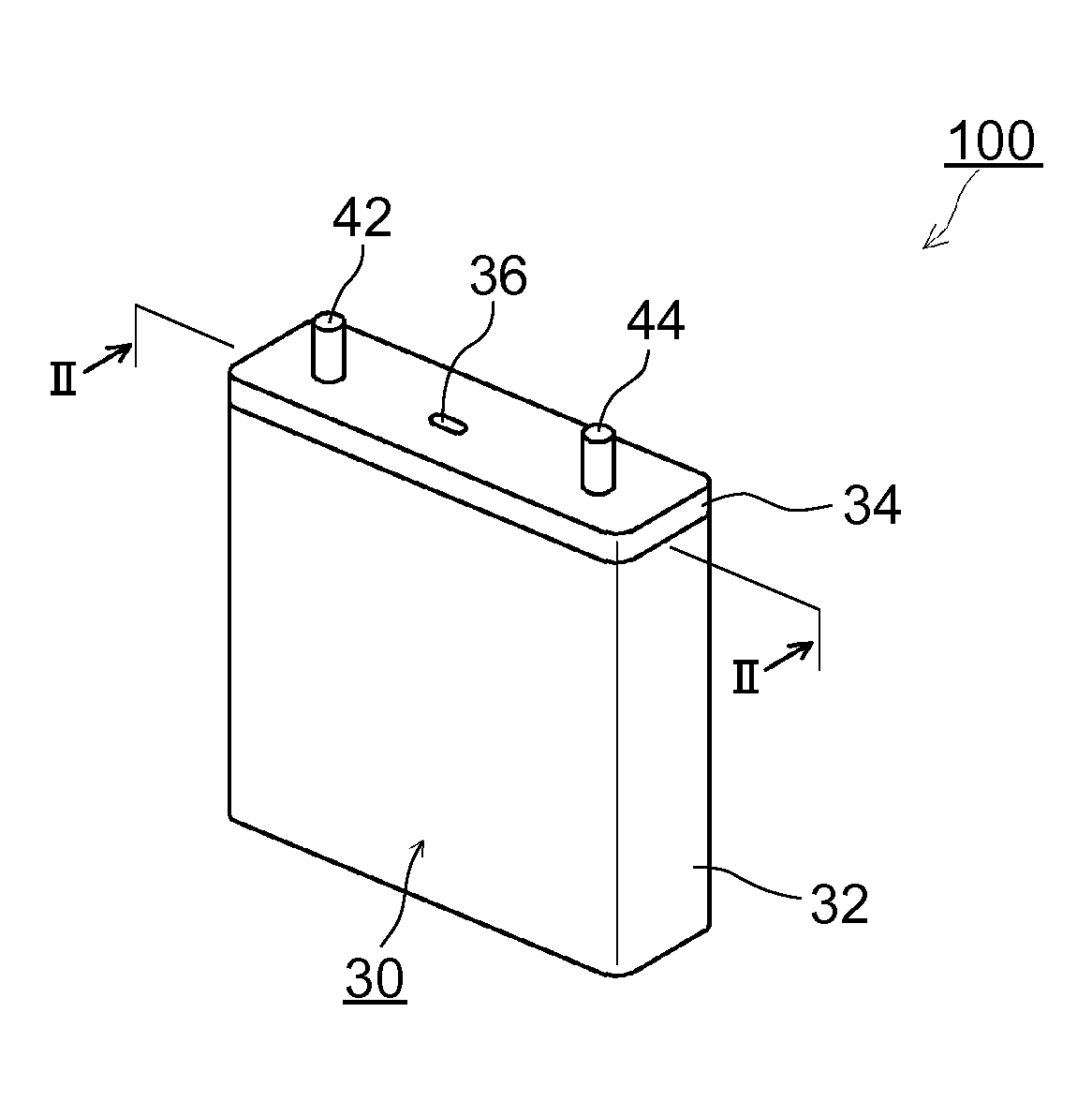
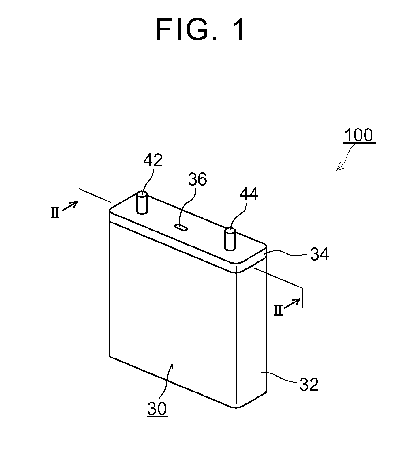
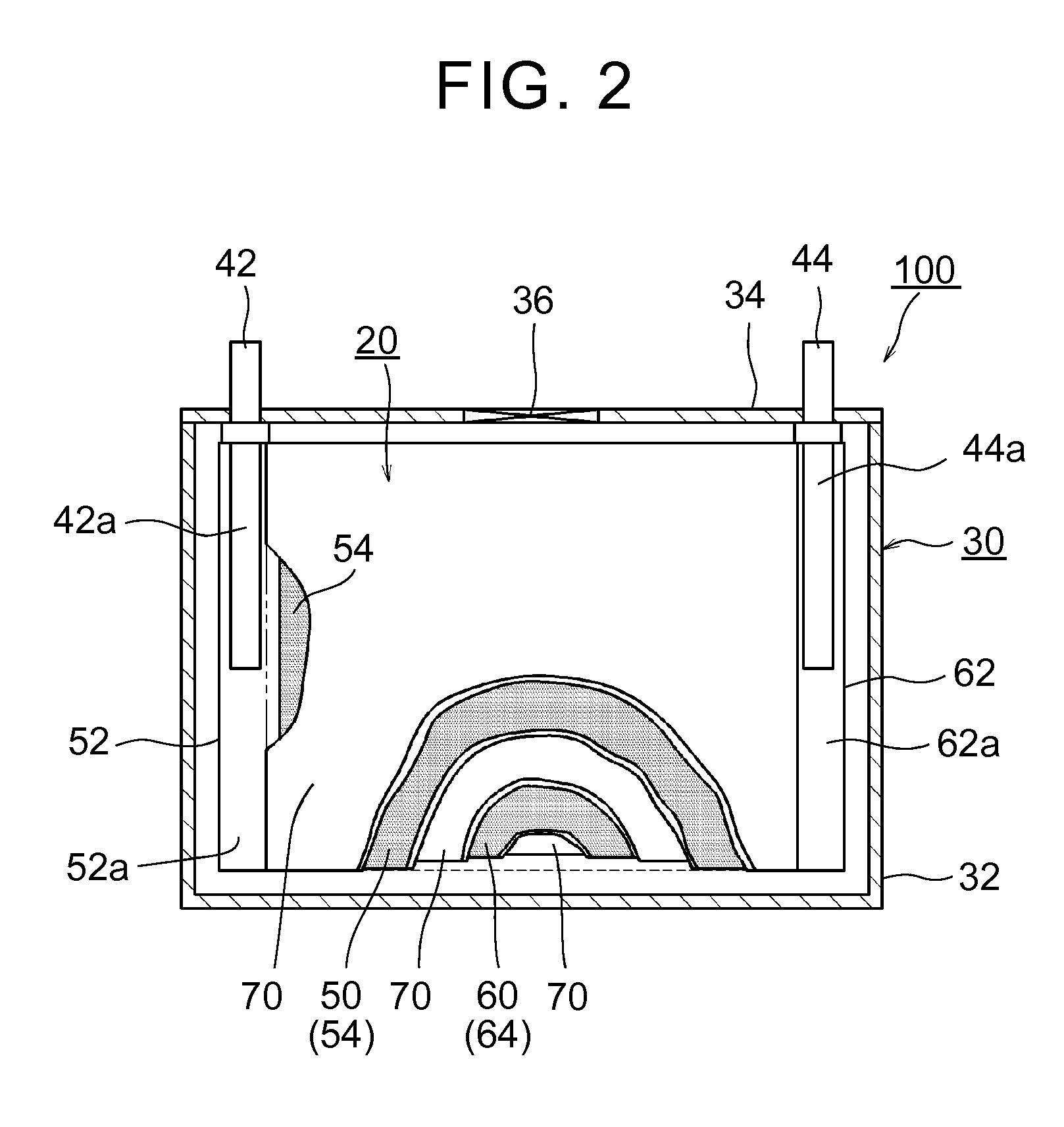
[0034]FIG. 1 is a view illustrating the external appearance of a lithium-ion secondary battery 100 according to an embodiment of the present invention. FIG. 2 is a sectional view sc...


PUM

PropertyMeasurementUnit
open-circuit voltageaaaaaaaaaa
BET specific surface areaaaaaaaaaaa
positive electrode potentialaaaaaaaaaa

Abstract

A lithium-ion secondary battery includes a positive electrode, a negative electrode and a non-aqueous electrolyte. The positive electrode includes a positive active material layer. The negative electrode includes a negative active material layer. The positive active material layer contains a positive active material and an inorganic phosphate compound. A BET specific surface area of the positive active material is 0.3 m2 / g to 1.15 m2 / g. The inorganic phosphate compound includes at least one of an alkali metal, an alkaline earth metal, and a hydrogen atom in a chemical formula. A content of the inorganic phosphate compound in the positive active material layer is 0.02 g / m2 to 0.225 g / m2 per unit surface area based on the BET specific surface area of the positive active material. The lithium-ion secondary battery allows an open-circuit voltage of the lithium-ion secondary battery to increase to 4.3 V or higher in terms of metal lithium.

Description

INCORPORATION BY REFERENCE[0001]The disclosure of Japanese Patent Application No. 2014-186754 filed on Sep. 12, 2014 including the specification, drawings and abstract is incorporated herein by reference in its entirety.BACKGROUND OF THE INVENTION[0002]1. Field of the Invention[0003]The present invention relates to a lithium-ion secondary battery and a method of manufacturing the same.[0004]2. Description of Related Art[0005]In recent years, a lithium-ion secondary battery has been used to drive a motor of an electric vehicle, a hybrid electric vehicle, a fuel cell vehicle, or the like or as an auxiliary power source thereof. Therefore, there is a demand for a higher output and a long service life after a large number of cycles.[0006]In order to achieve a high output, an increase in the voltage of a battery, that is, an increase in the upper limit voltage, during use is required. In order to achieve the increase in the voltage, for example, using a high-potential positive active mat...

Claims


Application Information

Patent Timeline
Patent Type & Authority Applications(United States)
IPC IPC(8): H01M4/505H01M4/04H01M4/36H01M4/50H01M4/52H01M4/525H01M4/58H01M10/0525
CPCH01M4/505H01M4/5825H01M4/525H01M4/502H01M2004/021H01M10/0525H01M4/366H01M4/0402H01M2004/028H01M4/523H01M4/139H01M10/058H01M4/0404H01M4/0435H01M10/4235Y02E60/10Y02P70/50
Inventor TAKEBAYASHI, YOSHITOMO
Owner TOYOTA JIDOSHA KK
Learn More