
Vehicle traction control

a technology of traction control and vehicle, applied in the direction of driver input parameters, external condition input parameters, vehicle condition input parameters, etc., can solve the problems of exacerbated problem, excessive slippage of one or more wheels, and difficult for novice drivers, so as to facilitate the maintenance of progress and high grip

Active Publication Date: 2016-03-24
JAGUAR LAND ROVER LTD
View PDF6 Cites 13 Cited by
  • Summary
  • Abstract
  • Description
  • Claims
  • Application Information

AI Technical Summary

Benefits of technology

This patent describes a system that controls the amount of torque applied to a vehicle's wheels in order to prevent excessive slip (flare) when the vehicle is accelerating on a surface with low grip. The system includes a brake control system and a powertrain control system that work together to control the overall amount of torque applied to the vehicle's wheels. This results in a smoother and more confident acceleration from rest, even on surfaces with low grip.

Problems solved by technology

Where a coefficient of friction (μ or ‘mu’) between vehicle tyres and ground is reduced or inconsistent, a conventional approach to vehicle launch may result in excessive slip of one or more wheels.
This is particularly problematic for novice drivers in off-highway conditions.
For example on sand, injudicious spinning of the wheels may cause the vehicle to excavate the sand and tail to gain sufficient traction to make progress over the sand.
The novice off-highway driver may not appreciate, from inside the vehicle, that one or more wheels are spinning, and the fitment of deep tread off-highway tyres may exacerbate this problem due to their tooth-like excavating properties.
Furthermore, in some situations excessive wheel spin can result in damage to the surface on which the vehicle is driving, particularly in the case of relatively fragile surfaces such as grass.
When a vehicle is in motion in slippery conditions, it may be relatively easy to induce excessive wheel spin and thereby lose traction, especially where variations in mu are experienced as the vehicle progresses.

Method used


Image

  • Vehicle traction control
  • Vehicle traction control
  • Vehicle traction control

Examples


Embodiment Construction

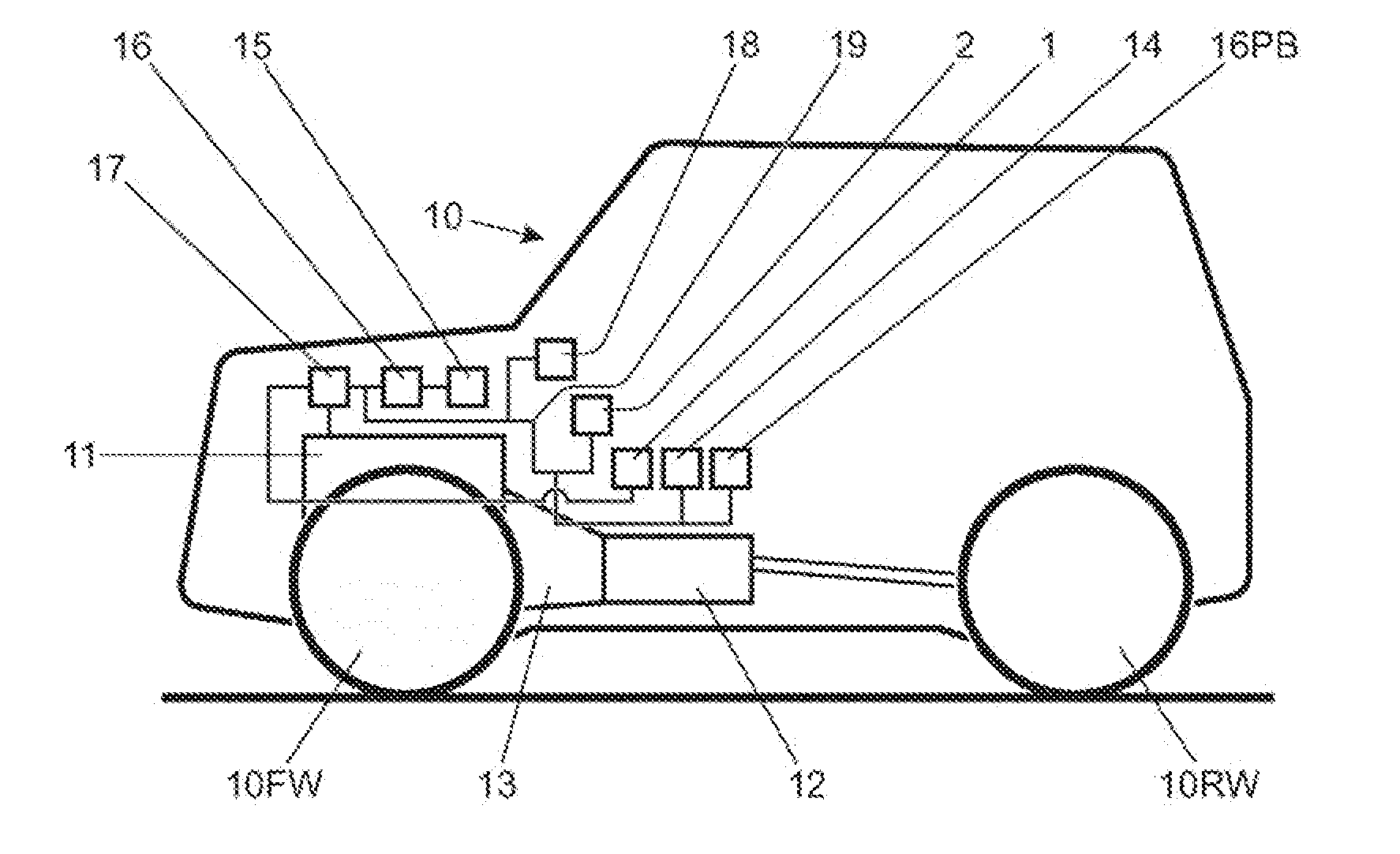
[0163]FIG. 1 is a schematic illustration of a vehicle 10 according to an embodiment of the present invention. The vehicle 10 has a prime mover or motor 11 in the form of an internal combustion engine. The engine 11 is coupled to a transmission 12 by means of a coupling 13. The coupling 13 is arranged to allow the transmission 12 progressively to reach a speed compatible with motor speed when the vehicle 10 is accelerated from rest. The coupling 13 is typically a friction clutch, torque converter or the like. An accelerator pedal 1 allows a driver to control an amount of torque developed by the motor 11 under the control of a powertrain controller 17 whilst a brake pedal 2 allows a driver to apply a braking system under the control of a brake controller 16.

[0164]The vehicle 10 includes a mode selector 14 operable by a driver to select a desired vehicle operating mode. These modes may comprise for example settings of suspension and drive train appropriate to different terrain conditio...


PUM


Abstract

A method of setting a vehicle in motion over a driving surface and / or maintaining motion of said vehicle over the driving surface implemented by a control system, said method comprising initiating motion control, initiating motion control comprising: commanding by the control system application of brake torque and drive torque to one or more wheels such that the vehicle is held stationary; subsequently initiating motion from rest whilst brake torque continues to be applied to the one or more wheels. The strategy may also be implemented to maintain vehicle progress on low friction surfaces. The vehicle driver may be commanded to vary a control input, such as accelerator pedal position, in order to facilitate the maintaining of progress.

Description

TECHNICAL FIELD[0001]The present invention relates to vehicle traction control and particularly, but not exclusively, to a system and method of improving traction control of a vehicle, for example moving a vehicle from rest, and maintaining vehicle progress in off-highway conditions. Aspects of the invention relate to a method, to a system and to a vehicle.BACKGROUND[0002]Moving a vehicle from rest in highway conditions on a dry asphalt surface is well understood. Where a coefficient of friction (μ or ‘mu’) between vehicle tyres and ground is reduced or inconsistent, a conventional approach to vehicle launch may result in excessive slip of one or more wheels. This is particularly problematic for novice drivers in off-highway conditions. For example on sand, injudicious spinning of the wheels may cause the vehicle to excavate the sand and tail to gain sufficient traction to make progress over the sand. The novice off-highway driver may not appreciate, from inside the vehicle, that on...

Claims


Application Information

Patent Timeline
Patent Type & Authority Applications(United States)
IPC IPC(8): B60W30/18B60W10/06B60W10/184
CPCB60W30/18172B60W10/06B60W10/184B60W50/082B60W50/14B60W30/18027B60W2710/0666B60W2710/182B60W2720/26B60W2530/10B60W2540/10B60W2720/106B60W2552/40B60W2552/05B60W2540/215Y02T10/72B60T8/175B60T8/3205B60W10/18
Inventor FAIRGRIEVE, ANDREWKELLY, JAMES
Owner JAGUAR LAND ROVER LTD
Learn More