
Microscope and method for 3D high-resolution localization microscopy with an enlarged measurement region

a high-resolution localization and microscopy technology, applied in the direction of fluorescence/phosphorescence, instruments, polarising elements, etc., can solve the problems of affecting the image of affecting the resolution of the image, and causing the photons emitted by the radiating fluorescence marker to interfere with each other, so as to achieve no meaningful resolution

Active Publication Date: 2016-03-24
CARL ZEISS MICROSCOPY GMBH
View PDF2 Cites 7 Cited by
  • Summary
  • Abstract
  • Description
  • Claims
  • Application Information

AI Technical Summary

Benefits of technology

The invention proposes a method to modify the way microscopy is done to enable the observation of deeper regions and to prevent the unwanted illumination of fluorescing markers. The method involves imaging the specimen in multiple image planes at different focal positions. By manipulating the point spread function and broadening the capture range, the method avoids the problem of unwanted illumination. The individual images from each pair of images taken at different focal positions can be easily joined together based on the position of the fluorescing markers in the depth direction. This allows for a more accurate indication of the depth position of the markers.

Problems solved by technology

One drawback of this method is that the local surroundings and orientation of a molecular dipole can also result in a distortion of the image of the radiating fluorescence marker, which has nothing to do with the depth position.
Here, photons emitted by the radiating fluorescence markers are caused to interfere with each other.
The drawback to this approach is that twice the number of individual images have to be recorded for the localization, namely, for each light sheet position the number of single images that would be needed during traditional PALM imaging.
Finally, as a rule no meaningful resolution is possible any more within the filtered overlap region.
In PAL microscopy, furthermore, an unwanted irradiation of the fluorescence markers can be a disadvantage, since the fluorescence markers often can only go through a very limited number of activation and / or excitation cycles.
In this regard, any irradiation not utilized for a high-resolution imaging is undesirable.
What is common to the above mentioned 3D localization methods is the problem of a limited capture range, i.e., the range in which molecules can be detected and localized without intervention at the objective.
This results in long recording time.
Furthermore, generally while producing such slices areas of the specimen are excited which are not even used for the imaging.
Fluorescence emitters which undergo the activation and / or excitation cycles but were not used for the localization generally can no longer be used for another measurement, so that a complete imaging of the specimen may be difficult if not impossible.

Method used


Image

  • Microscope and method for 3D high-resolution localization microscopy with an enlarged measurement region
  • Microscope and method for 3D high-resolution localization microscopy with an enlarged measurement region
  • Microscope and method for 3D high-resolution localization microscopy with an enlarged measurement region

Examples


Embodiment Construction

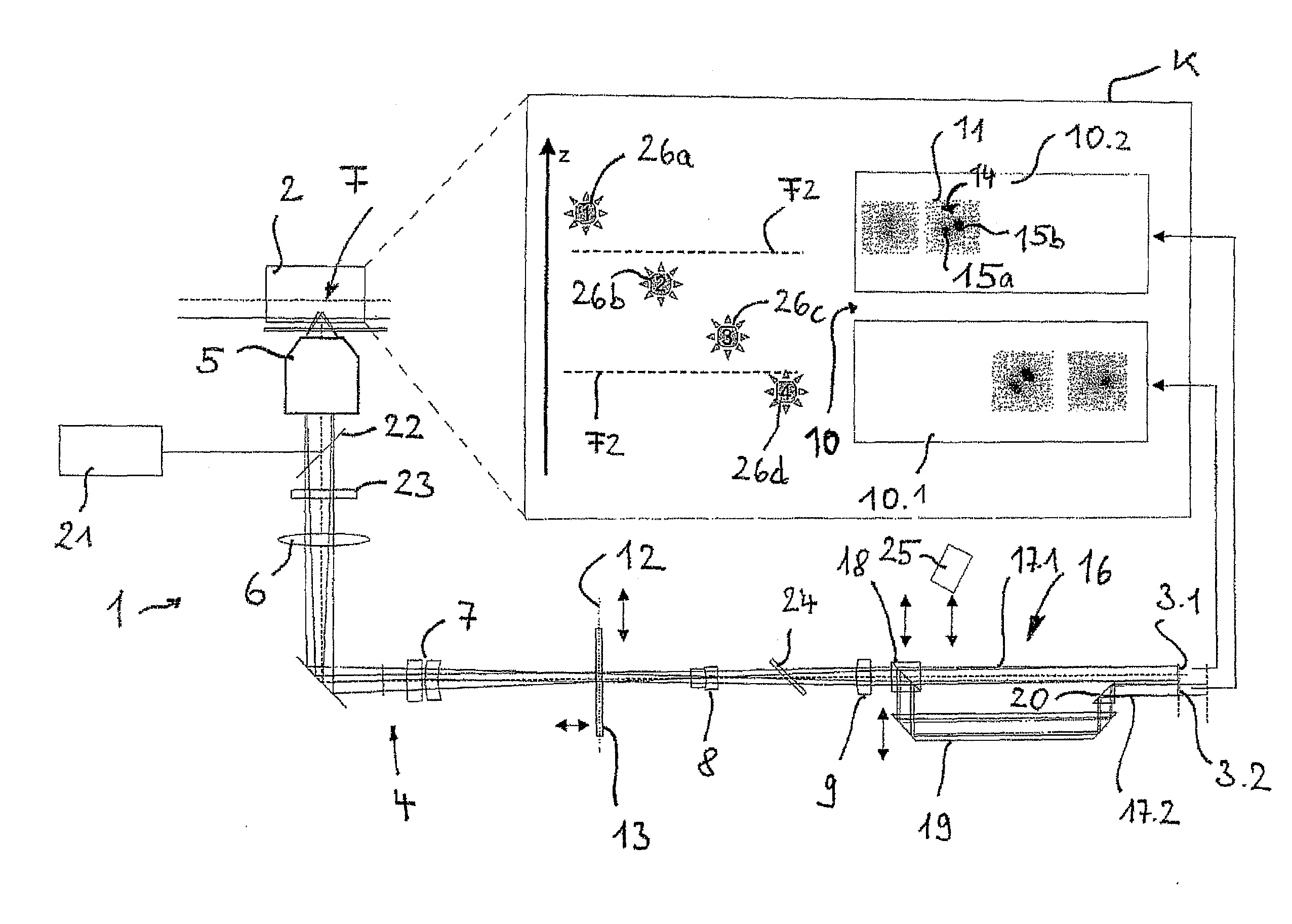
[0035]FIG. 1 shows a microscope 1 designed to image a specimen 2 by means of the PALM principle. The specimen 2 is imaged on two detectors 3.1, 3.2 by an imaging beam path 4. The imaging beam path 4 has an objective 5 as well as a tube lens 6, which through additional optics 7, 8, 9 project a region of the specimen 2 situated in a focal plane F onto the detectors 3.1, 3.2. The imaging beam path 4, as will be further explained below, has a different optical path lengths for the two detectors 3.1 and 3.2, so that the two detectors 3.1 and 3.2 are associated with different focal planes F. This will be further explained below. As a result, the two detectors 3.1 and 3.2 provide an individual image pair 10 consisting of two individual images 10.1 and 10.2. These are represented schematically in the box K. With the imaging layout described thus far, one would expect that a radiating fluorescence emitter in the specimen 2 appears as a circular spot in the individual image 10.1 or 10.2, whos...


PUM


Abstract

A microscope for high-resolution imaging of a sample in a depth direction and transversely thereto has an excitation beam path for illuminating a sample,—an imaging beam path with an objective and two detectors,—and a phase element. The phase element is situated in a pupil of the imaging beam path and has a different influence on two halves of the pupil cross section. The imaging beam path is split into two partial imaging beam paths downstream of the pupil as seen in the imaging direction, which partial imaging beam paths each lead to one of the two detectors. The two partial imaging beam paths have imaging lengths that differ by a specific wavelength difference such that the two detectors record images of the sample from two different focal planes, which are spaced apart by a distance in the depth direction.

Description

RELATED APPLICATIONS[0001]The present application is a U.S. National Stage application of International PCT Application No. PCT / EP2014 / 058451 filed on Apr. 25, 2014 which claims priority benefit of German Application No. DE 10 2013 208 415.3 filed on May 7, 2013, the contents of each are incorporated by reference in their entirety.FIELD OF THE INVENTION[0002]The invention pertains to a method of 3D high-resolution localization microscopy, wherein fluorescence emitters in a specimen are repeatedly excited to emit fluorescent radiation and individual images of the specimen are created with a microscope. The microscope has an imaging beam path with an optical resolution and a focal plane. The fluorescence emitters are excited to emit fluorescent radiation in such a way that at least one subset of the fluorescence emitters in each individual image is isolated so that the images of these fluorescence emitters can be separated within the optical resolution in the individual images.BACKGRO...

Claims


Application Information

Patent Timeline
IPC IPC(8): G02B21/36G01N21/64G02B5/30G02B21/16G02B21/18H04N13/20
CPCG02B21/367G02B21/16G02B21/18G01N21/6458G02B5/3083H04N13/02H04N13/0271G02B21/361G02B21/006H04N13/271H04N13/20
Inventor KALKBRENNER, DR., THOMAS
Owner CARL ZEISS MICROSCOPY GMBH
Learn More