Backlight unit and liquid crystal display device

a backlight unit and liquid crystal display technology, applied in semiconductor devices, lighting and heating apparatus, instruments, etc., can solve the problems of affecting the balance between the amount of blue light emitted by the light source and the amount of additional emitted light, and the light emitting efficiency is reduced, and the effect of increasing the amount of blue ligh

Inactive Publication Date: 2016-03-31
FUJIFILM CORP
View PDF3 Cites 10 Cited by
  • Summary
  • Abstract
  • Description
  • Claims
  • Application Information

AI Technical Summary

Benefits of technology

[0025]In one embodiment, the backlight unit comprises a control element that is capable of controlling the intensity of light emitted by at least one of the two or more light sources independently of the intensity of the light emitted by another light source. When the light source is a group of light sources containing two or more light sources of identical maximum emission wavelengths and angles of incidence as set forth above, it suffices for the control element to be able to control the intensity of the light emitted by at least one of the light sources classified as being in the same group of light sources independently of the intensity of the light emitted by a light source classified as being another light source, or for it to be able to independently control the intensity of the light emitted by two or more light sources classified as being in the same group of light sources. This embodiment also covers an embodiment in which individual light sources among all the light sources classified as being in the same group of light sources are not independently controlled, but the intensity of the light emitted by all the light sources classified a

Problems solved by technology

The reason for this is thought to be a decrease in light emitting efficiency due to deterioration of the phosphor over time, for example.
Scattering and changes in absorption of light by members constituting the backlight unit may also conceivably cause tinting of the white light emitted by the backlight unit.
For example, when the members constituting the backlight unit deteriorate over time and a transparent member becomes yellowish, the balance between the amount of blue light emitted by the light source and the amount of additional emitted light ends up changing, and the white light that is emitted by the backlight unit may conceivably become tinted.
However, controlling the amount of phosphor added and the like during the manufacturing of the wavelength conversion member as is described in Japanese Translated PCT Pate

Method used


Image

  • Backlight unit and liquid crystal display device
  • Backlight unit and liquid crystal display device
  • Backlight unit and liquid crystal display device

Examples


examples

[0113]The present invention will be more specifically explained on the basis of Examples below. The material, amount used, proportion, treatments, treating procedure, and the like shown in the following Examples can be appropriately modified as long as the modifications thereof do not depart from the gist of the present invention. Accordingly, the scope of the present invention should not be interpreted limitedly by the following Examples.

[0114]The following chromaticity was measured with a chromaticity luminance meter (SR-3 made by TOPCON Corp.).

[0115]Light sources 1 to 3 employed below were blue LED light sources that emitted light with a single peak having the maximum emission wavelength indicated below.

Light source 1: 455 nm

Light source 2: 465 nm

Light source 3: 440 nm

Preparation of Liquid Crystal Display Device 101

Comparative Example

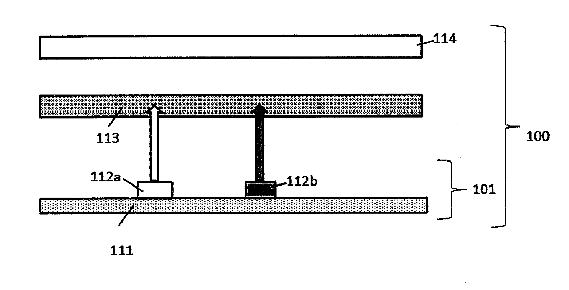
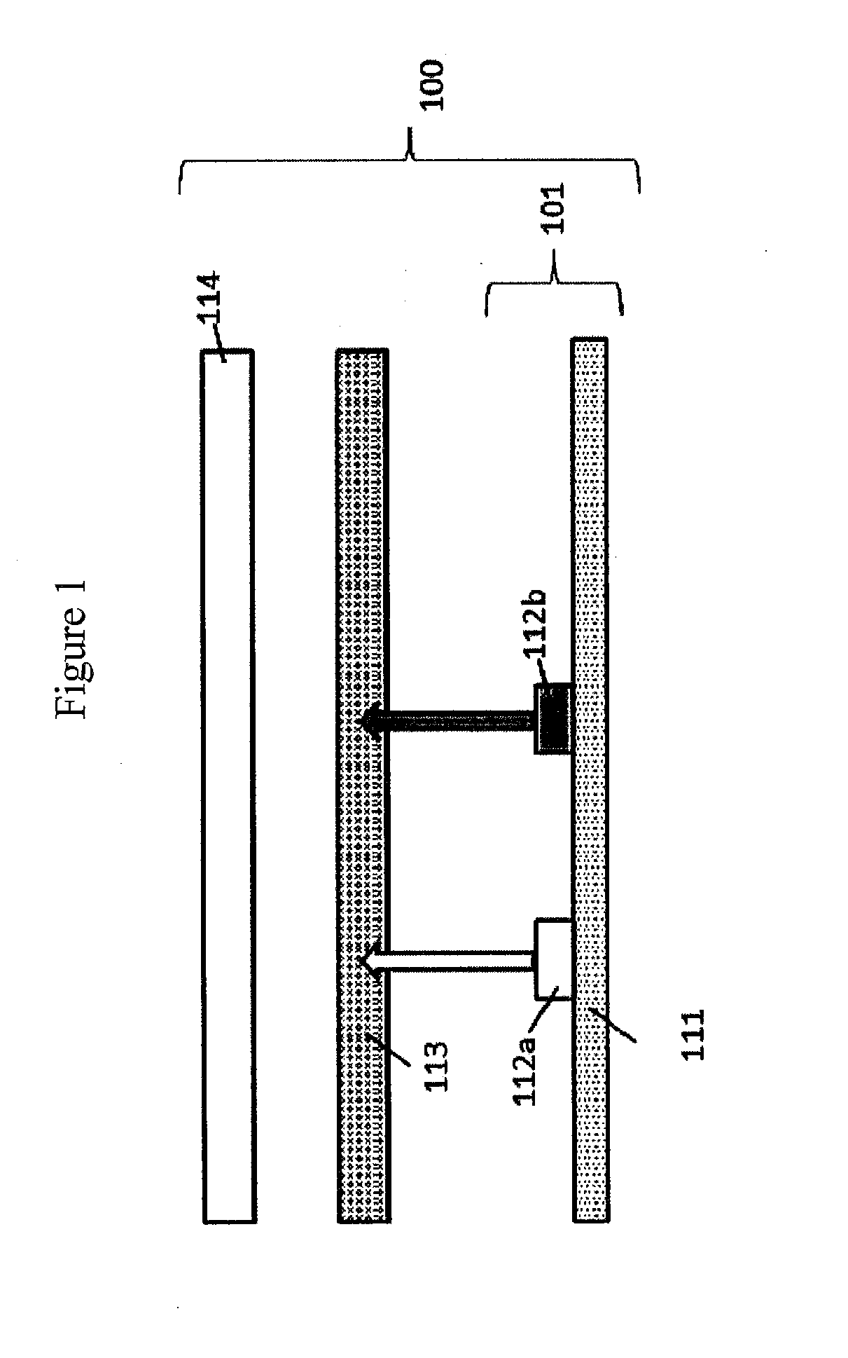
[0116]A wavelength conversion member in which barrier films were deposited on both surfaces of a wavelength conversion layer containing quantum dot ...

example

[0134]With the exception that two light sources in the form of light source 2 and light source 3 were simultaneously employed, in the same manner as in liquid crystal display devices 102 and 103, the intensity of the light emitted by each of the light sources was reduced by 50% from the initial setting state set in liquid crystal display devices 102 and 103.

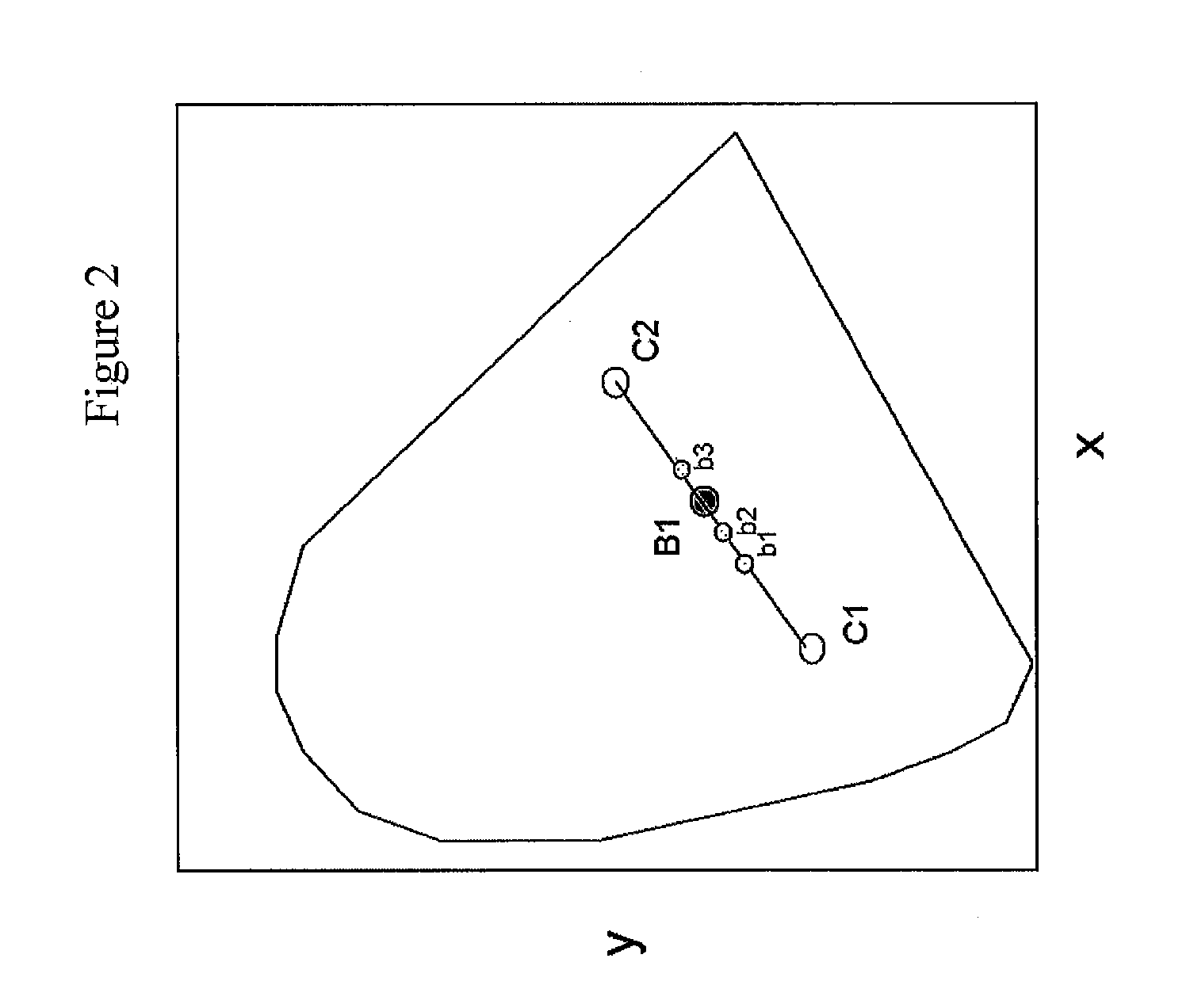
[0135]The intensity ratio of the light emitted by the two light sources was changed from the above state (specifically, the relative intensity of light source 2 was increased relative to the intensity of light source 3) to cause the backlight layer to emit untinted white light of ?c=0.33 and y=0.33. When this was adopted as the initial setting state and the wavelength conversion member was changed to a wavelength conversion member that had been changed over time, weakening the relative intensity of light source 2 relative to that of light source 3 made it possible to effect an adjustment to white light of x=0.33 and y=0.33 (see T...


PUM


Abstract

The backlight unit includes two or more light sources, and a wavelength conversion member positioned on each of optical paths of light emitted by the two or more light sources, wherein the wavelength conversion member includes a wavelength conversion layer containing at least a phosphor emitting green light when excited with exciting light and a phosphor emitting red light when excited with exciting light, and at least either maximum emission wavelengths or angles of incidence of entry into the wavelength conversion member of the light emitted by the two or more light sources differ.

Description

CROSS-REFERENCE TO RELATED APPLICATIONS[0001]This application claims priority under 35 U.S.C 119 to Japanese Patent Application No. 2014-202425 filed on Sep. 30, 2014. The above application is hereby expressly incorporated by reference, in its entirety.BACKGROUND OF THE INVENTION[0002]1. Field of the Invention[0003]The present invention relates to a backlight unit, and to a liquid crystal display device equipped with the same.[0004]The present invention further relates to a method of controlling the chromaticity of light emitted by a backlight unit.[0005]2. Discussion of the Background[0006]Flat panel displays such as liquid crystal display devices (also referred to as LCDs (liquid crystal displays), hereinafter) can consume little power and conserve space. Their use as image display devices has been increasing each year. A liquid crystal display device comprises at least a backlight unit and a liquid crystal panel.[0007]Backlight units containing light sources in the form of white ...

Claims


Application Information

Patent Timeline
IPC IPC(8): F21K99/00G02F1/1335F21V9/16H05B44/00
CPCG02F1/133603F21V9/16G02F2001/133614H05B33/0848F21K9/56G02F1/133614G02F2202/36
Inventor YONEYAMA, HIROYUKI
Owner FUJIFILM CORP
Why Eureka
Try Eureka