
Method for Hydrophobization of Surface of Silicon-Containing Film by ALD

a technology of atomic layer deposition and hydrophobic surface, which is applied in the direction of coating, chemical vapor deposition coating, metallic material coating process, etc., can solve the problems of increasing dielectric constant and/or leakage current, physical damage caused by chemical mechanical planarization, and drying etching and plasma ashing,

Active Publication Date: 2016-03-31
ASM IP HLDG BV
View PDF2 Cites 28 Cited by
  • Summary
  • Abstract
  • Description
  • Claims
  • Application Information

AI Technical Summary

Benefits of technology

The present invention relates to a method of depositing a SiO or SiOC film onto a low-k film using atomic layer deposition (ALD). The method includes adding a material that makes the surface of the SiO or SiOC film hydrophobic, such as dimethylaminotrimethylsilane, isopropylaminotrimethylsilane, or hexamethyldisilazane, to the surface as the last step of the deposition treatment. The invention also includes using plasma-enhanced atomic layer deposition (PEALD) to form the SiO or SiOC film by cycles of supplying an ALD material, purging the material, and applying RF power. The use of the silicon-containing material, which has a single Si—N bond and at least one Si-CxHy bond or Si—H bond in its molecule, helps to make the surface of the SiO or SiOC film hydrophobic. The method may provide better stability and reliability for the low-k film during subsequent processing steps.

Problems solved by technology

Dielectric films are susceptible to damage during their manufacturing processes, thereby increasing dielectric constants and / or leakage currents.
Such process-related damage includes damage caused by dry etching and plasma ashing, and washing with chemicals, and physical damage by chemical mechanical planarization (CMP), etc.
Such porous low-k films are highly susceptible to damage during an etching process for patterning or the like, and when the films are damaged, the dielectric constant values increase.
However, although damaged surfaces can be restored to a certain degree by the above methods using a hydrocarbon film, restoration is insufficient depending on the degree of damage.
Further, a hydrocarbon film can seal pores of the damaged surfaces, but the hydrocarbon film does not have sufficient barrier function as a pore-sealing film against a barrier metal although it can inhibit diffusion of chemicals such as toluene to a certain degree.

Method used


Image

  • Method for Hydrophobization of Surface of Silicon-Containing Film by ALD
  • Method for Hydrophobization of Surface of Silicon-Containing Film by ALD
  • Method for Hydrophobization of Surface of Silicon-Containing Film by ALD

Examples


example 1

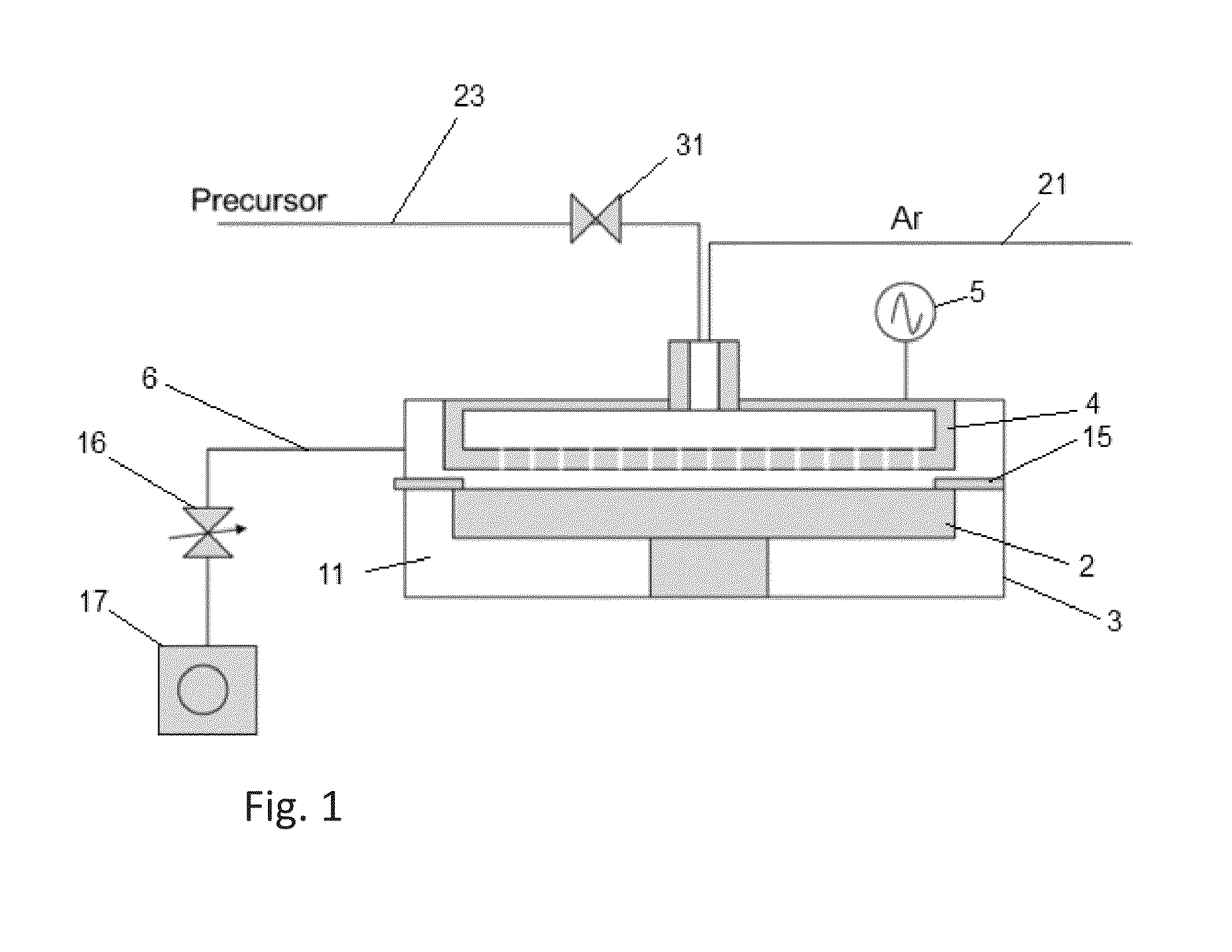
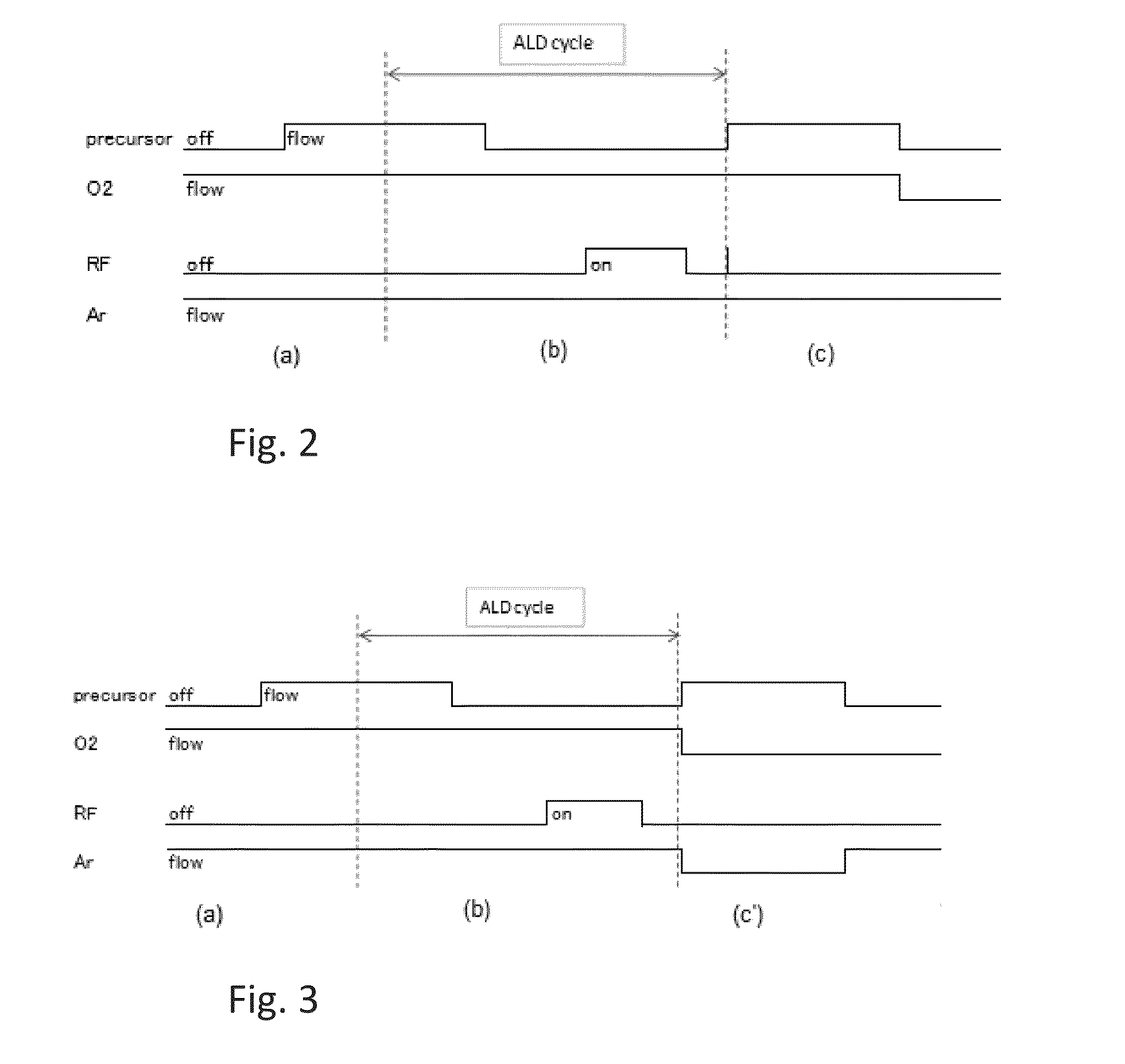
[0054]In a manner substantially similar to that in Comparative Example 1, a damaged ELK film was prepared, which had a dielectric constant of 3.0. The damaged ELK was subjected to the pore-sealing cycles under the conditions shown in Table 7 using dimethylaminotrimethylsilane (DMATMS) to obtain a pore-sealed ELK film. Next, the pore-sealed ELK film was subjected continuously to a hydrophobization step in the reaction chamber under the conditions shown in Table 8 to treat the pore-sealed surface of the film with a hydrophobic atomic layer. The process sequence illustrated in FIG. 2 was used herein.

TABLE 7(the numbers are approximate)Pore-sealing conditionsSubstrate temperature250°C.Pressure200 PaReactant gasO2Flow rate of reactant 30 sccmgas (continuous)Dilution gasArFlow rate of dilution 500 sccmgas (continuous)PrecursorDMATMSPrecursor pulse (supply time)1 sec at 100 sccmPurge upon precursor pulse3 secRF frequency13.56 MHzRF power50 WRF power pulse1 secPurge upon the RF power pulse1...

example 3

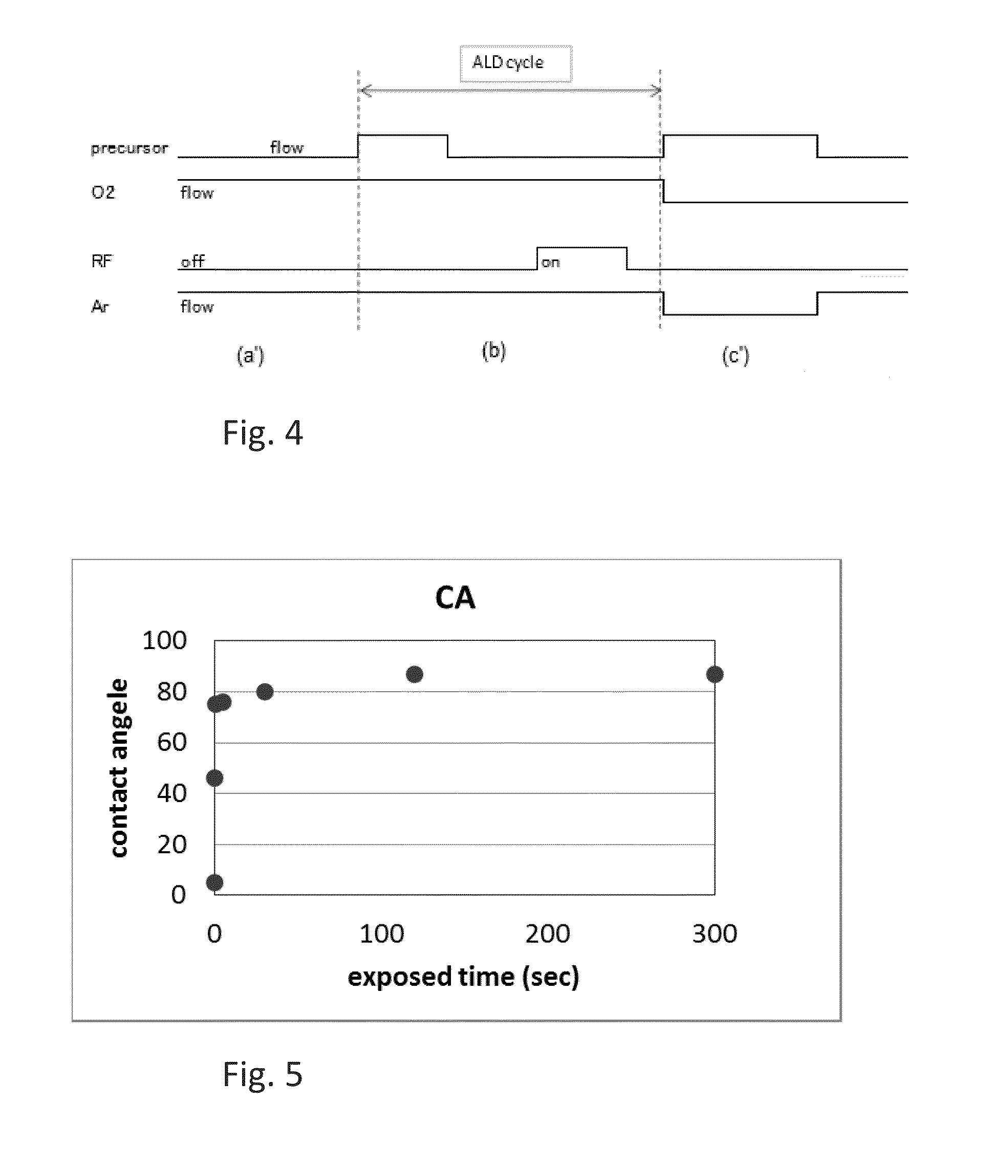
[0060]In a manner substantially similar to that in Example 1, a pore-sealed ELK film was prepared and subjected continuously to a surface-treating step (hydrophobization step) in the reaction chamber under conditions which were the same as in Example 1 except that the gas-exposure time (precursor supply time) varied from 0 sec to 300 sec (i.e., 0, 0.1, 0.5, 1.0, 30, 120, and 300 sec). The contact angle of each resultant treated surface is shown in FIG. 5. As shown in FIG. 5, the contact angle was drastically changed toward a hydrophobic state at a gas-exposure time of 0.5 sec, and the contact angle reached 80° at a gas-exposure time of 30 sec, i.e., rendering the surface hydrophobic. Thereafter, the contact angle appeared to reach a plateau in a range of 80° to 90°.

examples 4 and 5

[0061]In a manner substantially similar to that in Example 2, a damaged ELK film was prepared, and the damaged ELK was subjected to the pore-sealing cycles (the number of cycles was changed as shown in Table 13), and then, the pore-sealed ELK film was subjected continuously to the surface hydrophobization step in the reaction chamber. The ELK film in Example 4 had an original k-value of 2.3 and a pore size of about 1 nm, and the ELK film in Example 5 had an original k-value of 2.0 and a pore size of about 3 nm. The ELK films in Examples 4 and 5 were subjected to a chemical diffusion test where the substrate was submerged in a liquid chemical (ethanol) for 5 minutes, and then a cross section of the substrate was observed to see if the chemical penetrated through the surface and diffused toward the inside the substrate. The results are shown in Table 13.

TABLE 13Thickness of pore-sealing film Original(the number of ALD cycles)k-value0 nm0.5 nm1 nm1.5 nm(pore size)(0 cycles)(5 cycles)(1...


PUM

PropertyMeasurementUnit
thicknessaaaaaaaaaa
contact angleaaaaaaaaaa
thicknessaaaaaaaaaa

Abstract

A method is for hydrophobization of a surface of a silicon-containing film by atomic layer deposition (ALD), wherein the surface is subjected to atmospheric exposure. The method includes: (i) providing a substrate with a silicon-containing film formed thereon; and (ii) forming on a surface of the silicon-containing film a hydrophobic atomic layer as a protective layer subjected to atmospheric exposure, by exposing the surface to a silicon-containing treating gas without exciting the gas. The treating gas is capable of being chemisorbed on the surface to form a hydrophobic atomic layer thereon.

Description

BACKGROUND[0001]1. Field of the Invention[0002]The present invention generally relates to a method for repairing process-related damage of a dielectric film by cyclic processes, particularly to a method for hydrophobization of a surface of a silicon-containing film by atomic layer deposition (ALD).[0003]2. Description of the Related Art[0004]Dielectric films are indispensable to increasing processing speed of semiconductor devices and lowering power consumption of the devices. Dielectric films are susceptible to damage during their manufacturing processes, thereby increasing dielectric constants and / or leakage currents. Such process-related damage includes damage caused by dry etching and plasma ashing, and washing with chemicals, and physical damage by chemical mechanical planarization (CMP), etc. Particularly, in advanced devices, dielectric films are porous and have low dielectric constant values. Such porous low-k films are highly susceptible to damage during an etching process ...

Claims


Application Information

Patent Timeline
Patent Type & Authority Applications(United States)
IPC IPC(8): H01L21/02
CPCH01L21/0228H01L21/02123H01L21/02126H01L21/02164H01L21/02274H01L21/0234H01L21/02359H01L21/02362H01L21/3105C23C16/45542C23C16/56
Inventor KOBAYASHI, AKIKONAKANO, AKINORIISHIKAWA, DAIMATSUSHITA, KIYOHIRO
Owner ASM IP HLDG BV
Learn More