High-torque wind turbine

a high-torque, wind turbine technology, applied in the direction of machines/engines, stators, liquid fuel engines, etc., can solve the problems of limited power output, limited performance at low-, and limited power output of small turbine blades, so as to increase the airflow, increase the torque or power output, and increase the effect of airflow

Inactive Publication Date: 2016-04-07
RODGERS JAMES L +1
View PDF3 Cites 4 Cited by
  • Summary
  • Abstract
  • Description
  • Claims
  • Application Information

AI Technical Summary

Benefits of technology

[0071]It would also be advantageous some embodiments to provide a turbine that has a square or rectangular frame that surrounds the outer cowling, or the outer cowling and frame are made as one element, and the frame helps capture additional air by having flat external edges or surfaces that can mounted directly against roof, wall or other surfaces in order to increase the airflow in order to provide additional torque or power output.
[0072]It would also be advantageous to provide a turbine that can receive air directly into the extended blades and that is directed by the center deflector, the outer cowling and the outer frame into the extended blades in order to further increase the airflow in order to provide additional torque or power output.
[0073]It would also be advantageous to provide a turbine that has air foil type blades, sail type blades or a combination of blade types in order to operate to create maximum speed, maximum torque or some mix of capability in order to maximize its output for a particular range of wind or airflow speed and output use and loading.
[0074]It would also be advantageous to provide a turbine that can keep the same, step up or step down the output speed or torque in order to be optimized at a given wind speed in order to efficiently drive or operate a water pump to pump water for use or storage,

Problems solved by technology

However, these prior turbines have significant limitations that limit their performance at low-wind speeds, particularly wind speeds of 12 to 15 mph or less.
Therefore, the few blades in large turbines are generally a necessary and significant design compromise due to limited blade mounting area, extreme hub loading and blade angle control requirements.
This is particularly true in order to survive storms, which in turn limits their potential power output, particularly at lower wind speeds.
The few blades in small turbine are also generally limited by the some of the same factors, although not to the extremes of large turbines having significantly greater weight and wind force.
The resulting few blades in both large and small turbines limit their performance, particularly at lower wind speeds.
The amount of torque generated by the blade portions near the axis is limited by their airfoil or sail blade effectiveness and the short length of their moment arm relative to the turbine axis.
However, their few numbers and small cross-sectional area to the wind f

Method used


Image

  • High-torque wind turbine
  • High-torque wind turbine
  • High-torque wind turbine

Examples


Embodiment Construction

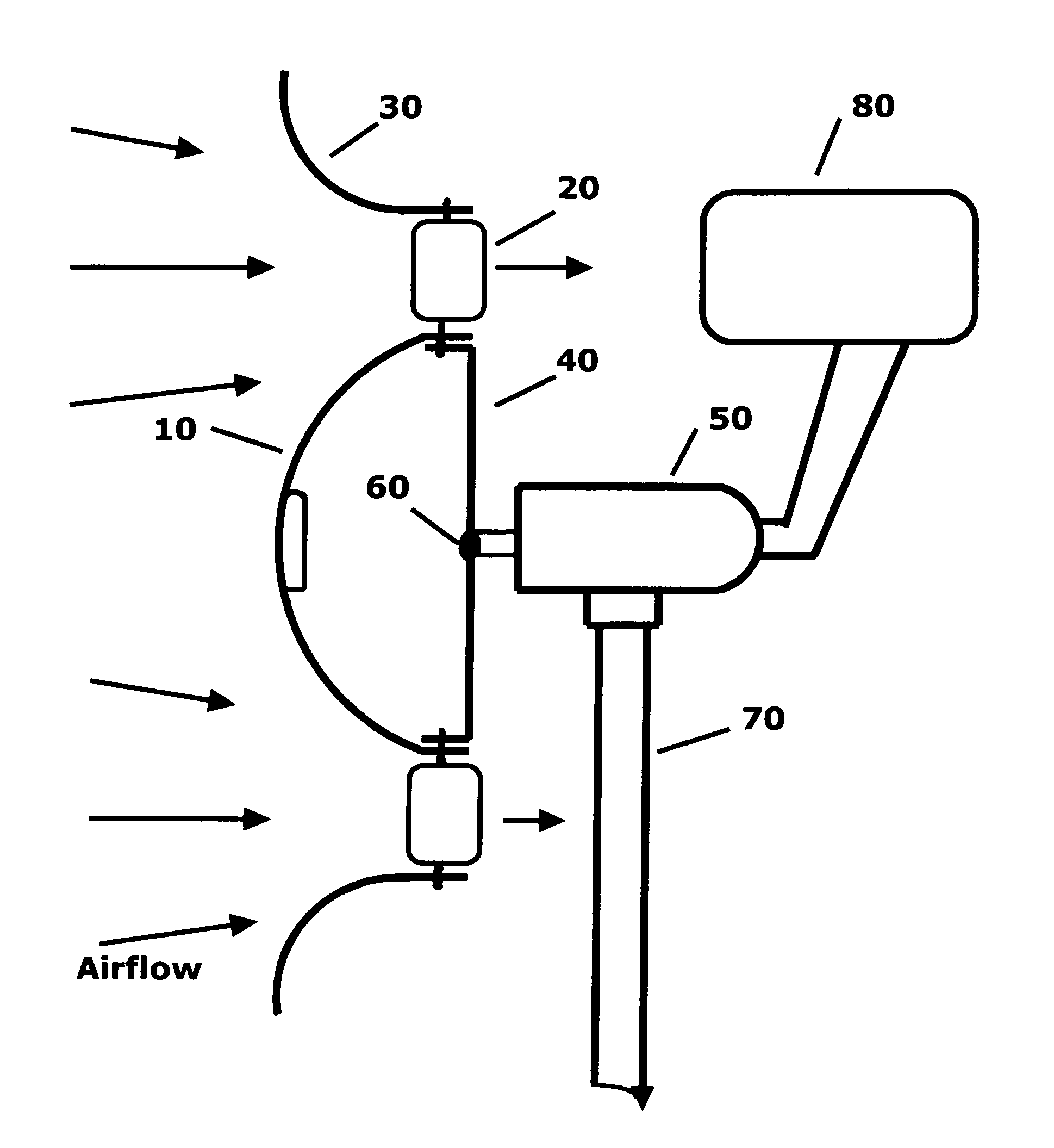
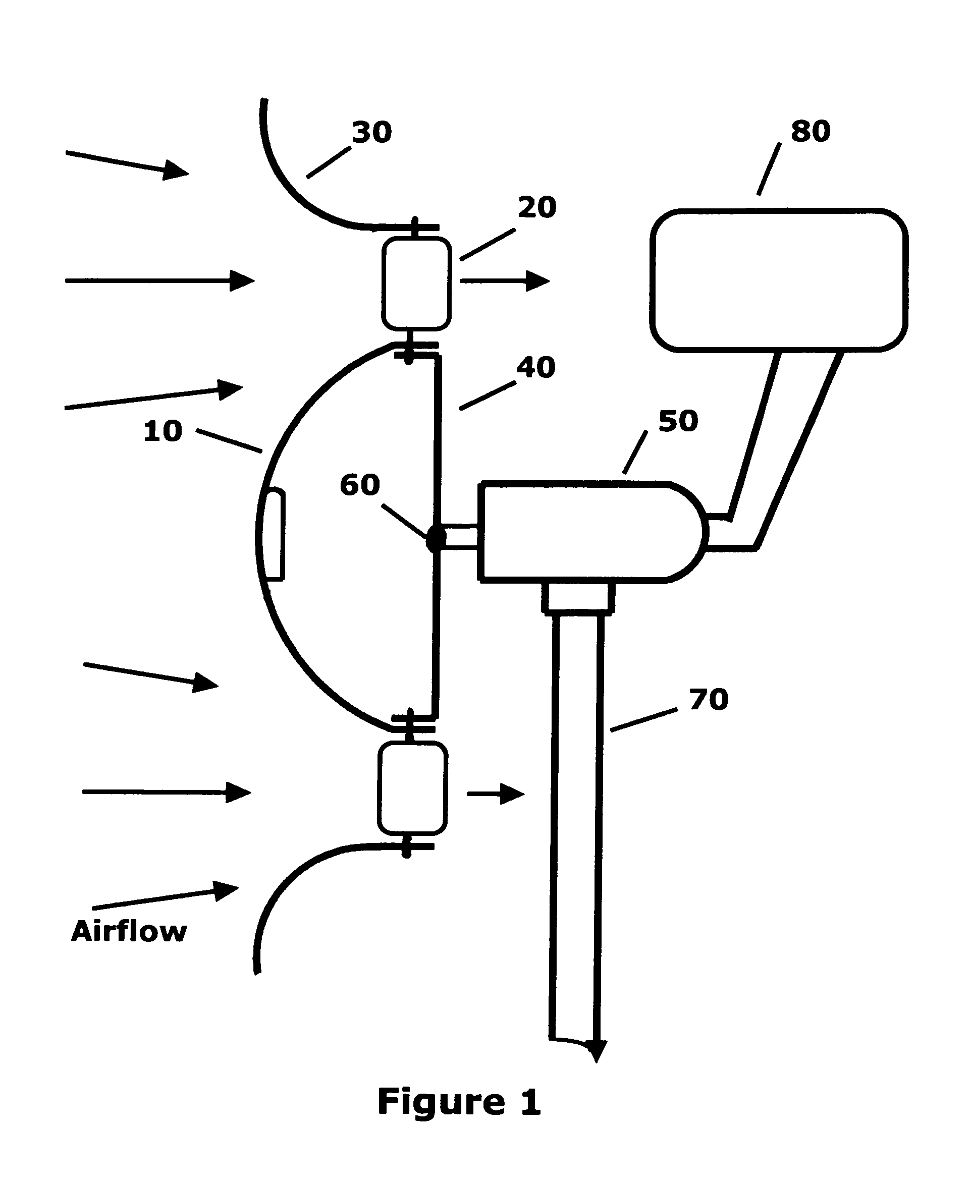
[0083]FIG. 1 is a is a side cross view in accordance with the invention without an external frame, consisting of center dome 1010, extended blades 1820, surrounding cowling 1230, mounting plate 40, axis 60 mechanical output, generator 50 or other means of power or power storage output, with mount 70 and tail 80.

[0084]The center dome 1010 serves to receive wind or airflow and then deflect it outward to the extended blades 1820.

[0085]The surrounding cowling 1230 serves to receive wind beyond the blades and deflect it inward to the extended blades 18 and also contain the air deflected outward by the center dome 1010.

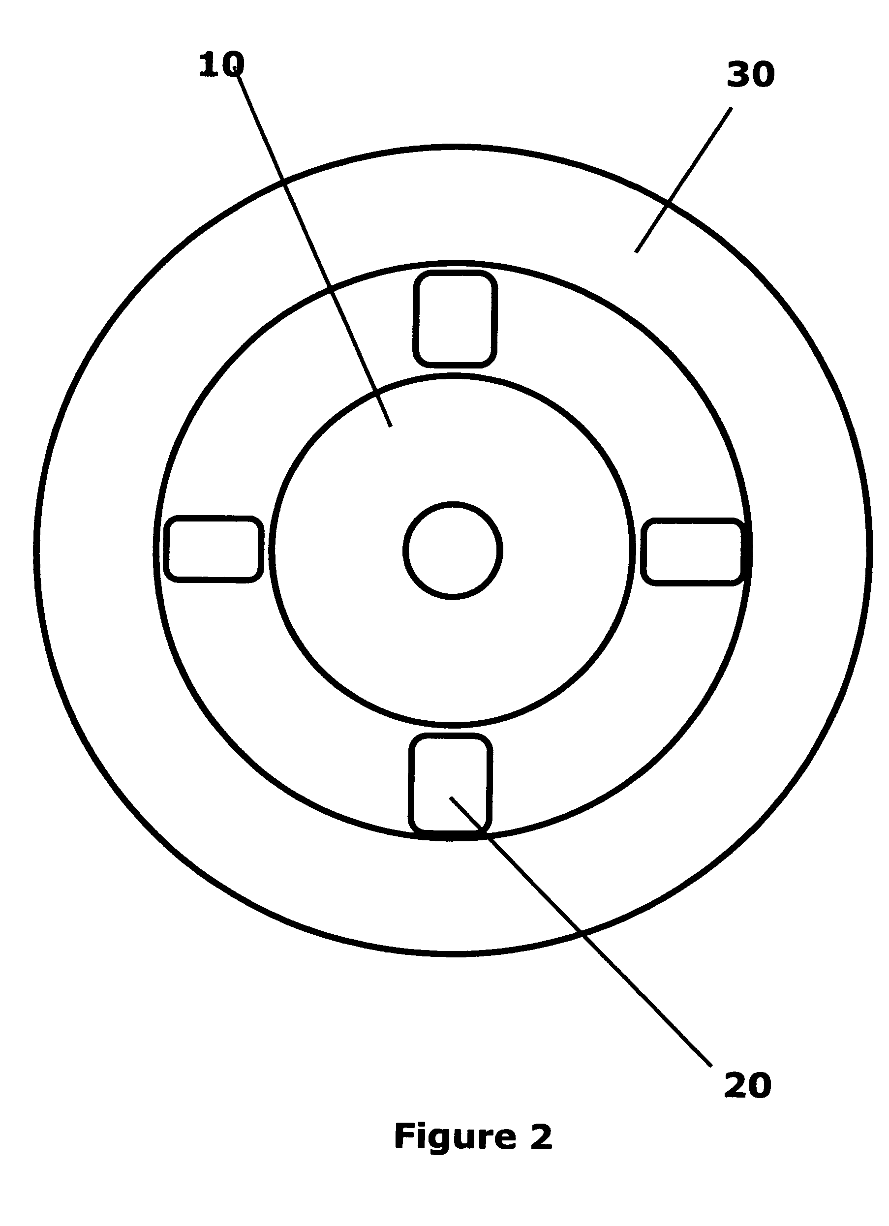
[0086]FIG. 2 is a front view in accordance with the invention without an external frame, showing center dome 1010, extended blades 1810, surrounding cowling 1230 with mount 70.

[0087]FIG. 3 is a side cross view in accordance with the invention with an external frame, consisting of center dome 1010, extended blades 1820, surrounding cowling 1230, mounting plate 40, axis 60 me...


PUM


Abstract

A high-torque turbine system receives and converts low to higher speed wind or airflow into mechanical work or electric power; consisting of a number of sail or airfoil blades or blade portions located near the outer periphery having extended moment arms for increased torque, that rotate around an center axis that is parallel to the airflow, wherein the blades receive wind directly, from a center deflector that directs wind received in the center outward to the blades, or from airflow directed externally from man-made, natural or structural sources, wherein the turbine system outputs mechanical work or electrical power.

Description

RELATED APPLICATIONS[0001]The present application is a continuation-in-part application of U.S. provisional patent application, Ser. No. 503027981, filed Mar. 30, 2012, for HIGH-TORQUE WND TURBINE, by James L. Rodgers, Barry H. Soloway, included by reference herein and for which benefit of the priority date is hereby claimed.FIELD OF THE INVENTION[0002]The present invention relates to wind or airflow driven turbines and, more particularly, to a propeller type horizontal axial-flow high-torque wind turbine, having a mechanical or an electrical generator output, with increased torque and efficiency at low-to moderate wind speeds.BACKGROUND OF THE INVENTION[0003]Prior wind axial-flow turbines with a generator output typically employ two to five narrow airfoil propeller-type blades that rotate perpendicularly around an axis. The propellers face the wind or airflow in order for them to receive and convert its kinetic energy into electrical power.[0004]The blades are generally made as lon...

Claims


Application Information

Patent Timeline
IPC IPC(8): F03D1/04F03D1/06F03D9/00
CPCF03D1/04F03D1/0691F03D9/001F03D9/002F03D9/25F03D9/28Y02E10/72F03D9/20
Inventor RODGERS, JAMES L.SOLOWAY, BARRY H.
Owner RODGERS JAMES L
Why Eureka
Try Eureka