

Electrode paste production method
- Summary
- Abstract
- Description
- Claims
- Application Information
AI Technical Summary
Benefits of technology
Problems solved by technology
Method used
Image

Examples
example 1
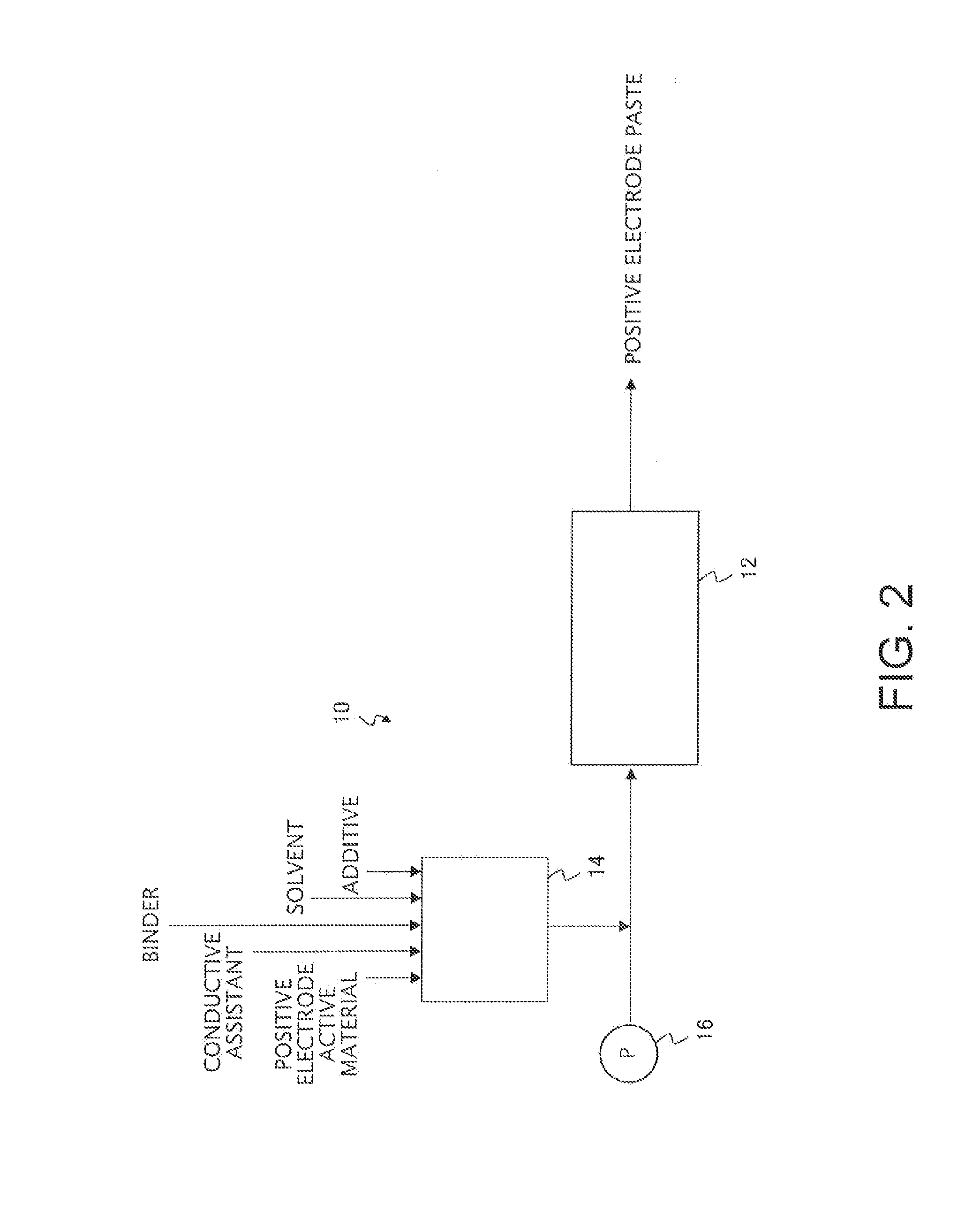
[0066]In the manner illustrated in FIG. 2, a mixture (solid content concentration: 70% by mass) obtained by mixing a solid fraction containing 90 parts by mass of a lithium-nickel-manganese complex oxide (LiNi0.5Mn1.5O4) as a positive electrode active material, 6 parts by mass of acetylene black as a conductive assistant, 3 parts by mass of polyvinylidene fluoride (PVDF) as a binder and 1 part by mass of lithium phosphate (volume-average particle size D50v=3 μm) as an additive, with N-methyl-2-pyrrolidone (NMP) as a solvent was kneaded and dispersed by a high shear force (8,000 kJ / L) using a micromixer (Nanovater, manufactured by Yoshida Kikai Co., Ltd.), thus obtaining a positive electrode paste (the micromixing treatment step).
[0067]Using the thus obtained paste, a positive electrode active material layer was formed on an aluminum foil using a die coating method, thus obtaining a positive electrode plate.
[0068]As described below, the obtained electrode was evaluated for the capaci...
example 2
[0071]In the manner illustrated in FIG. 3, 99 parts by mass of a lithium-nickel-manganese complex oxide (LiNi0.5Mn1.5O4) as a positive electrode active material and 1 part by mass of lithium, phosphate as an additive were used, and the additive was coated onto the surface of the positive electrode active material using a coating treatment device (Nobilta, manufactured by Hosokawa Micron Corporation), thus obtaining a coated active material (the coating treatment step).
[0072]Subsequently, a mixture (solid content concentration: 70% by mass) obtained by mixing a solid fraction containing 91 parts by mass of the obtained coated active material, 6 parts by mass of acetylene black as a conductive assistant, and 3 parts by mass of polyvinylidene fluoride (PVDF) as a binder, with N-methyl-2-pyrrolidone (NMP) as a solvent was kneaded and dispersed by a high shear force (8,000 kJ / L) using a micromixer (Nanovater, manufactured by Yoshida Kikai Co., Ltd.), thus obtaining a positive electrode p...
example 3
[0074]In the manner illustrated in FIG. 4, 99.5 parts by mass of a lithium-nickel-manganese complex oxide (LiNi0.5Mn1.5O4) as a positive electrode active material and 0.5 parts by mass of lithium phosphate as an additive were used, and the additive was coated onto the surface of the positive electrode active material using a coating treatment device (Nobilta, manufactured by Hosokawa Micron Corporation), thus obtaining a coated active material.
[0075]Subsequently, a mixture (solid content concentration: 70% by mass) obtained by mixing a solid fraction containing 90.5 parts by mass of the obtained coated active material, 6 parts by mass of acetylene black as a conductive assistant, 3 parts by mass of polyvinylidene fluoride (PVDF) as a binder and 0.5 parts by mass of lithium phosphate as an additive, with N-methyl-2-pyrrolidone (NMP) as a solvent was kneaded and dispersed by a high shear force (8,000 kJ / L) using a micromixer (Nanovater, manufactured by Yoshida Kikai Co., Ltd.), thus o...
PUM
| Property | Measurement | Unit |
|---|---|---|
| Percent by mass | aaaaa | aaaaa |
| Pressure | aaaaa | aaaaa |
| Pressure | aaaaa | aaaaa |
Abstract
Description
Claims
Application Information