Electrode catalyst

a technology of electrodes and catalysts, applied in the field of electrode catalysts, can solve the problems of oxidative decomposition of carrier carbon, achieve the effects of improving cycle durability, high oxygen dissociation capacity, and improving orr activity

Inactive Publication Date: 2016-04-14
TOYOTA JIDOSHA KK
View PDF0 Cites 3 Cited by
  • Summary
  • Abstract
  • Description
  • Claims
  • Application Information

AI Technical Summary

Benefits of technology

[0030]The reason why advantageous effects, such as the improvement in ORR activity and the improvement in cycle durability, are achieved is thought to be due to the following mechanism. Firstly, oxygen and water are activated on the metal catalyst containing a Ag element, which has high oxygen dissociation capacity and water dissociation capacity, and the reaction intermediate (OOH−) is produced (first 2-electron reduction reaction). Subsequently, the reaction intermediate is effectively spilled over to the perovskite-type oxide catalyst containing La, Mn and O elements, which has high activity for reducing the reaction intermediate. Then, the reaction intermediate is reduced, which leads to the completion of the reaction (second 2-electron reduction reaction). At this time, a concerted reaction, in which these reactions proceed effectively, occurs and therefore high oxygen reduction reaction activity (first 2-electron reduction reaction+second 2-electron reduction reaction) is achieved on the whole. In this case, since the reaction intermediate (OOH−) produced in the first 2-electron reduction reaction is quickly moved to the second 2-electron reduction reaction, the oxidative decomposition of carrier carbon is suppressed.
[0031]As described above, according to the present embodiment, an electrode catalyst having higher oxygen reduction reaction activity, in which carrier carbon is not oxidatively decomposed in an oxygen reduction reaction, can be obtained.
[0032]Hereinafter, the electrode catalyst according to the present embodiment (hereinafter, also simply referred to as “present electrode catalyst”) will be described in detail.
[0033]The perovskite-type oxide catalyst in the present electrode catalyst is located on carbon i.e., a carrier, and contains La, Mn and O elements. The perovskite-type oxide catalyst is not particularly limited as long as it is a material that has high activity for reducing the reaction intermediate (OOH−), i.e., a material that enables the above-described second 2-electron reduction reaction. For example, La that enters into the A-site of the perovskite-type structure may be partially or completely substituted with other rare earth elements and alkali earth metal elements. In addition, Mn that enters into the B-site of the perovskite-type structure may be partially or completely substituted with other 3d transition metal elements (Ti, V, Cr, Fe, Co, Ni). Among them, LaMnO3 is preferable. In any case, inevitable impurities and dopants that do not cause an adverse impact on the above-described characteristics may be contained.
[0034]The ratio of the perovskite-type oxide catalyst with respect to the whole electrode catalyst (carrier carbon+perovskite-type oxide catalyst+metal catalyst), i.e., the carried amount of the perovskite-type oxide catalyst is 5 to 95 mass %, preferably 30 to 60 mass % and more preferably 40 to 50 mass %. When the carried amount of the perovskite-type oxide catalyst is too much, since carrier carbon and the metal catalyst become insufficient, the electron conductivity is decreased and the first 2-electron reduction reaction becomes difficult to occur. In contrast, when the carried amount of the perovskite-type oxide catalyst is too little, since the first 2-electron reduction reaction occurs but the second 2-electron reduction reaction does not sufficiently occur, carrier carbon is oxidized and decomposed by the attack of a peroxide (OOH−or the like) i.e., a reaction intermediate produced in the first 2-electron reduction reaction. Thus, the durability of the electrode catalyst is decreased and the reaction rate is decreased.
[0035]The particle diameter of the perovskite-type oxide catalyst is not particularly limited as long as the perovskite-type oxide catalyst has high activity for reducing the reaction intermediate, i.e., enables the above-described second 2-electron reduction reaction. The particle diameter of the perovskite-type oxide catalyst is preferably 1 to 30 nm, and more preferably 2 to 20 nm. When the particle diameter is too small, the activity is decreased due to sintering during the reaction process. When the particle diameter is too large, the reaction area is decreased and high activity cannot be obtained.

Problems solved by technology

However, when the electrode catalyst as disclosed in Patent Literature 1 is used as an air electrode of an air battery, carrier carbon is oxidatively decomposed at the time of discharge of the air battery, i.e., in an oxygen reduction reaction on the air electrode.

Method used


Image

  • Electrode catalyst
  • Electrode catalyst
  • Electrode catalyst

Examples


example 1

(1) Example 1

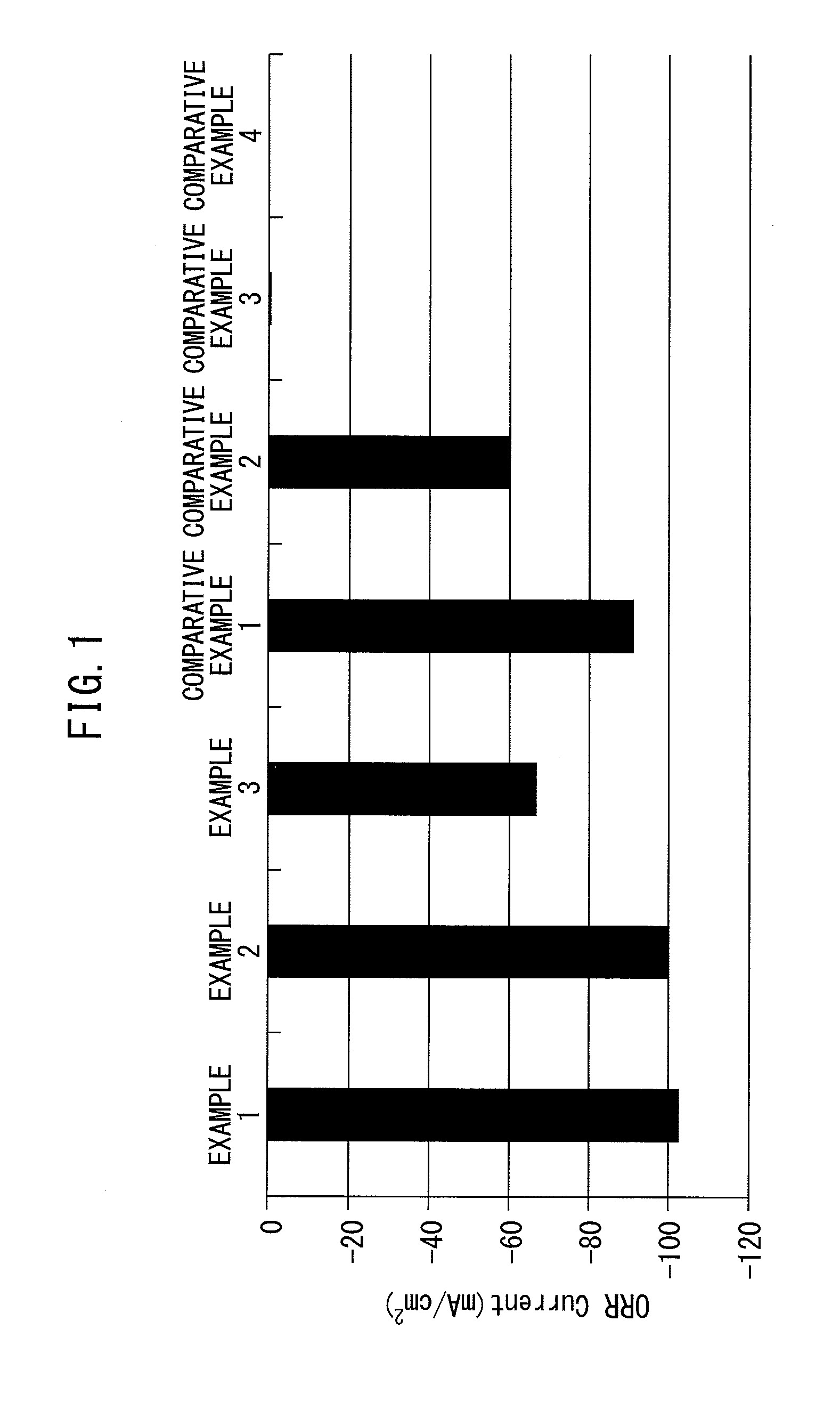
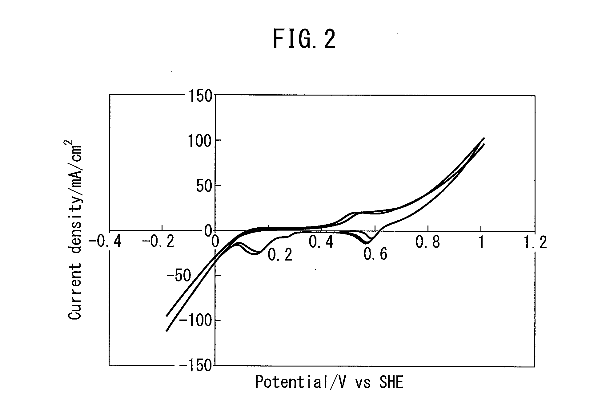
[0088]In the electrode catalyst of Example 1, extremely-good oxygen reduction activity was obtained. The details are as follows. FIG. 2 is a graph illustrating a CV measurement result of the electrode catalyst of Example 1. The vertical axis represents a (oxygen reduction reaction) current, and the horizontal axis represents a potential (vs. SHE). In the electrode catalyst of Example 1, an extremely-high oxygen reduction reaction current (−103 mA / cm2) and a high cycle property (difference of oxygen reduction reaction currents between cycles was small) were obtained. The reason is believed to be that the electrode catalyst of Example 1 included the perovskite-type oxide catalyst containing La, Mn and O elements and the metal catalyst containing a Ag element, which were located on the carrier containing C. In contrast, in the electrode catalyst in which the spinel-type oxide such as CuCoO4 and Co3O4 and Ag were supported on carrier carbon of Comparative Examples 3 and 4 a...

example 2

(2) Example 2

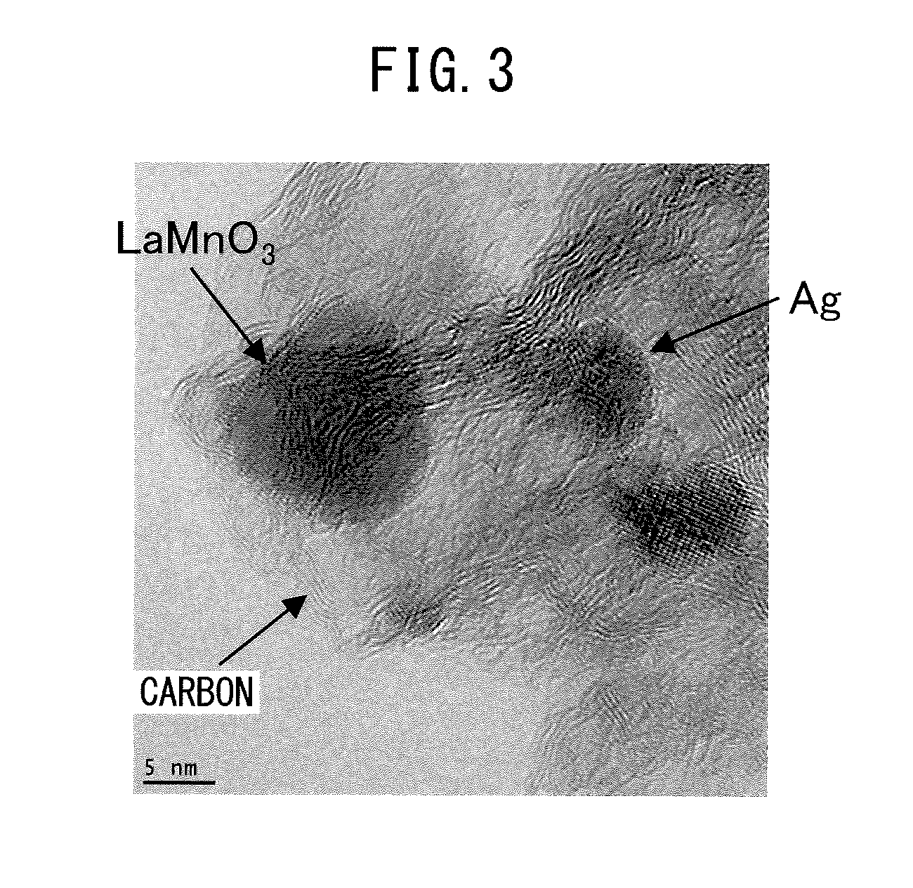
[0093]Also in the electrode catalyst of Example 2, extremely-good oxygen reduction activity was obtained. Specifically, in the electrode catalyst of Example 2, as illustrated in a CV measurement result of FIG. 5, an extremely-high oxygen reduction reaction current (−100 mA / cm2) and a high cycle property (difference of oxygen reduction reaction currents between cycles was small) were obtained. The reason is basically the same as the case of Example 1. In other words, this is because the perovskite-type oxide catalyst containing La, Mn, and O elements and the metal catalyst containing a Ag element were included on the C carrier, LaMnO3 and Ag were located extremely near, for example, within a range of 20 nm or less, as illustrated in a TEM photograph of FIG. 6, Ag was not encaptured or included by LaMnO3, the most part was a LaMnO3 phase as illustrated in an XRD measurement result of FIG. 7, and carbon was not burned down by the air calcination at the time of manufacturin...

example 3

(3) Example 3

[0095]Also in the electrode catalyst of Example 3, good oxygen reduction activity was obtained. Specifically, in the electrode catalyst of Example 3, as illustrated in a CV measurement result of FIG. 8, a high oxygen reduction reaction current (−67.4 mA / cm2) and a high cycle property (difference of oxygen reduction reaction currents between cycles was small) were obtained. The reason is basically the same as the case of Example 1. However, since the air calcination temperature was higher compared with the cases of Examples 1 and 2, the particle diameter tended to become slightly larger due to sintering of LaMnO3 and carbon tended to be slightly burned down, as illustrated in a TEM photograph of FIG. 9. Accordingly, the ORR current was slightly decreased compared with the electrode catalysts of Examples 1 and 2.

[0096]As described above, the above-described electrode catalyst of Example 3 has good characteristics.


PUM

PropertyMeasurementUnit
distanceaaaaaaaaaa
particle diameteraaaaaaaaaa

Abstract

An electrode catalyst includes a carbon (C) carrier; a perovskite-type oxide catalyst containing lanthanum (La), manganese (Mn), and oxygen (O) elements; and a metal catalyst containing a silver (Ag) element. The perovskite-type oxide catalyst is located on the carrier and the metal catalyst is also located on the carrier.

Description

BACKGROUND OF THE INVENTION[0001]1. Field of the Invention[0002]The present invention relates to an electrode catalyst.[0003]2. Description of the Related Art[0004]An air battery is known as a means for storing and effectively using electrical energy. An air battery is characterized by capable of having large energy density in principle because a cathode (positive electrode) active material does not need to be arranged in a battery case and an anode (negative electrode) active material can be arranged in the most of the battery case. In other words, an air battery can increase the capacity and therefore is attracting attention.[0005]An electrode catalyst that oxidizes / reduces oxygen is used for an air electrode of an air battery, which is an electrode catalyst manufactured by a reverse-micelle method and is disclosed in Patent Literature 1, for example. This electrode catalyst includes a C (carbon) carrier; and a perovskite-type oxide catalyst located on the carrier and containing L...

Claims


Application Information

Patent Timeline
Patent Type & Authority Applications(United States)
IPC IPC(8): H01M4/90
CPCH01M4/9083H01M4/90H01M4/9016H01M4/9033H01M4/9058H01M12/06B01J23/688B01J37/03B01J2523/00C01G45/1264C01P2002/34C01P2002/50C01P2002/72C01P2002/88C01P2004/04C01P2004/64C01P2006/40B01J2523/18B01J2523/3706B01J2523/72
Inventor NITTA, IWAO
Owner TOYOTA JIDOSHA KK
Why Eureka
Try Eureka