Method of manufacturing unit fuel cell

a fuel cell and unit technology, applied in the field of unit fuel cell manufacturing, can solve the problems of thermal deformation of the support frame made of resin and reduced battery performan

Active Publication Date: 2016-04-14
TOYOTA JIDOSHA KK
View PDF3 Cites 6 Cited by
  • Summary
  • Abstract
  • Description
  • Claims
  • Application Information

AI Technical Summary

Benefits of technology

[0008]According to one aspect of the present invention mentioned above, it is possible to reliably integrate the support frame, the gas diffusion layer and the membrane electrode assembly without exposing the membrane electrode assembly and without deforming the support frame.

Problems solved by technology

However, there is a possibility that the support frame made of a resin is thermally deformed when heating, compressing and integrating the support frame, the outer portion of the adhesive layer and the membrane electrode assembly.
Thus, there is a possibility that the battery performance is reduced.

Method used


Image

  • Method of manufacturing unit fuel cell
  • Method of manufacturing unit fuel cell
  • Method of manufacturing unit fuel cell

Examples


Embodiment Construction

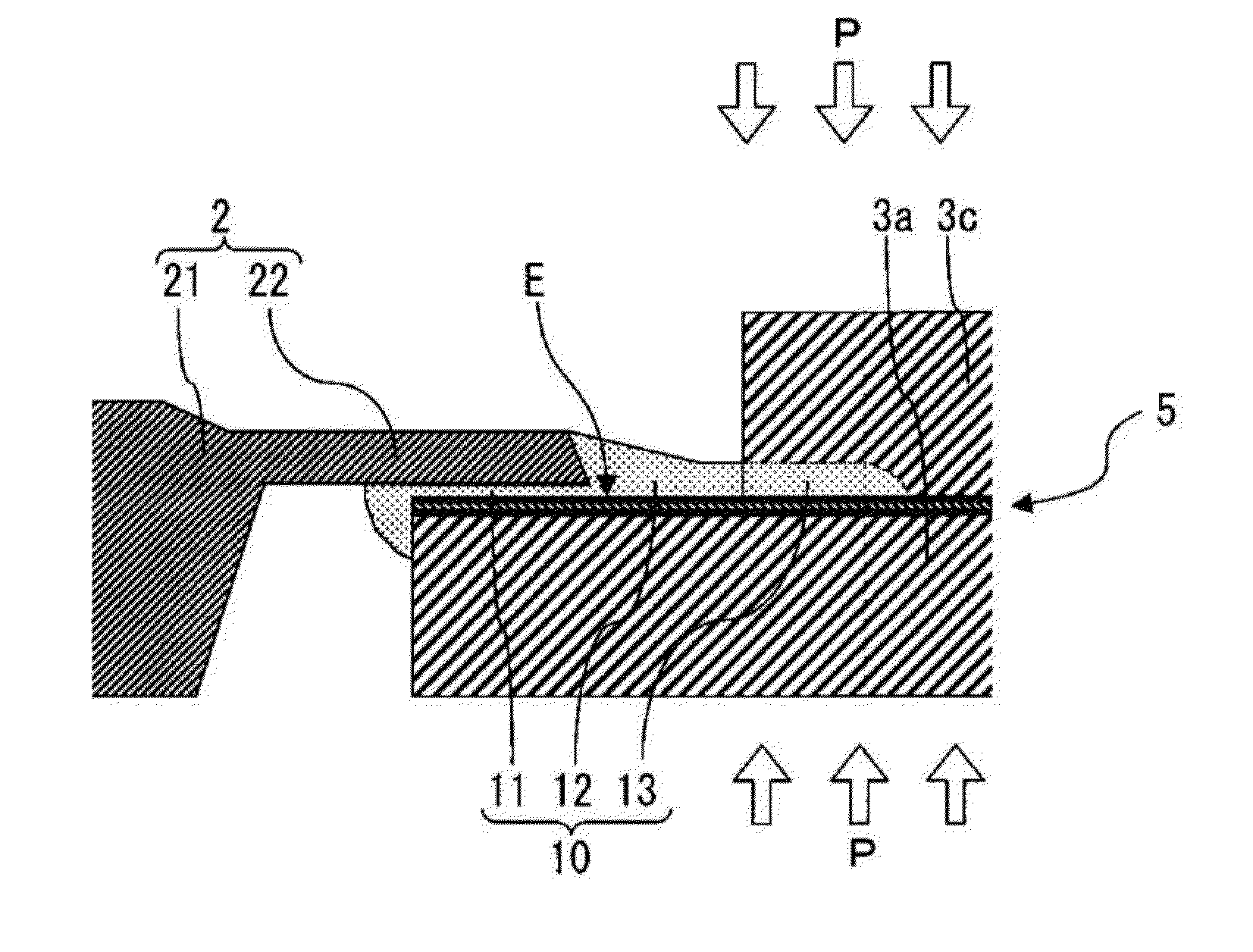
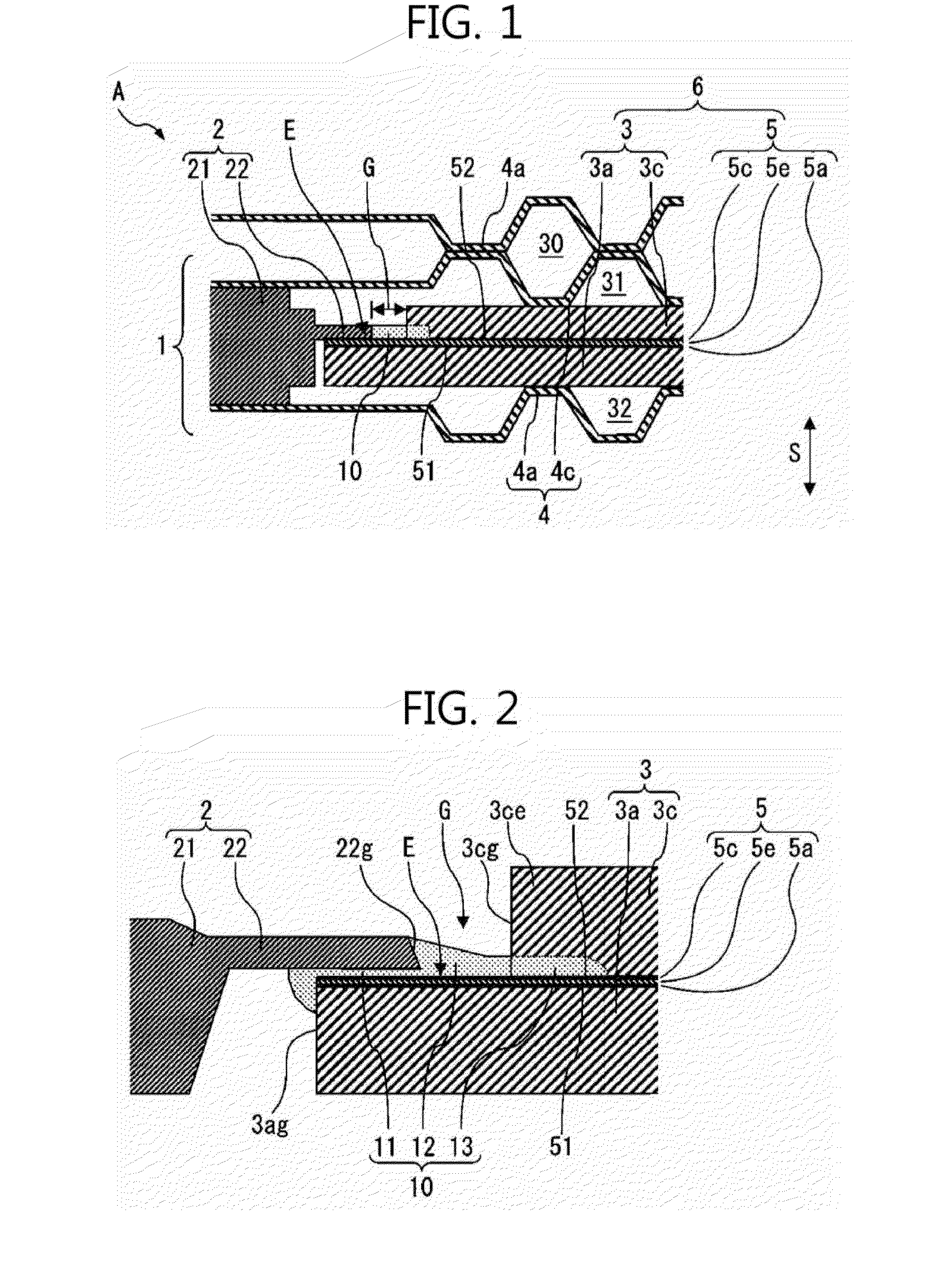
[0022]FIG. 1 is a partial sectional view illustrating a configuration example of a fuel cell stack A including a unit fuel cell 1. Referring to FIG. 1, the fuel cell stack A is formed by a stacked body in which a plurality of unit fuel cells 1 is stacked in a thickness direction S of the unit fuel cells 1. The unit fuel cell 1 generates electric power using an electrochemical reaction of a fuel gas and an oxidant gas which are supplied to the unit fuel cell 1. The electric power generated in the unit fuel cell 1 is taken out to the outside of the fuel cell stack A via a plurality of wiring lines (not illustrated) extending from terminal plates (not illustrated) disposed at the opposite ends of the stacked body to the outside of the fuel cell stack A. The electric power taken out from the fuel cell stack A is supplied to, for example, an electric motor for driving an electric vehicle or a capacitor.

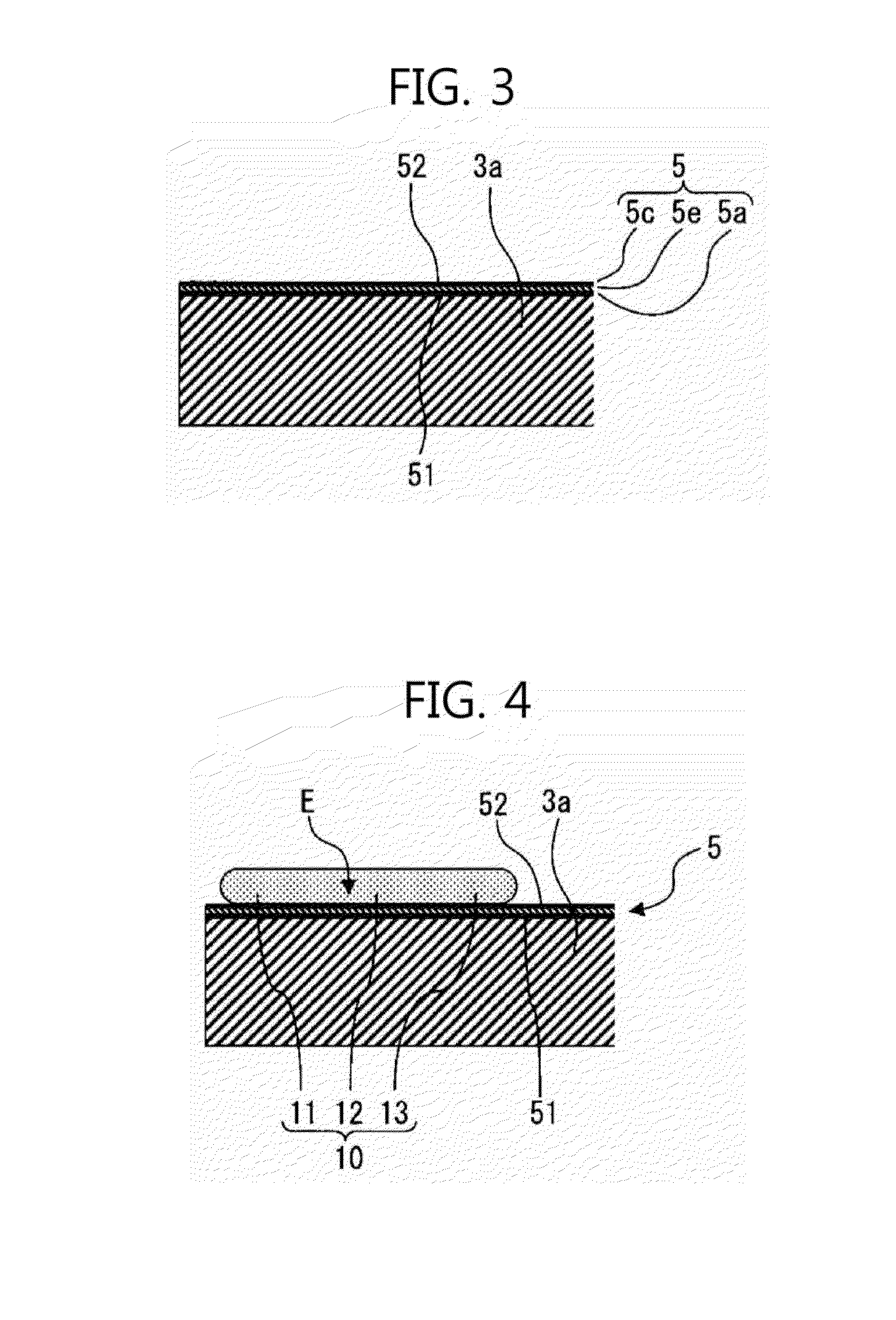
[0023]The unit fuel cell 1 includes a membrane electrode assembly 5 in which electrode...


PUM

PropertyMeasurementUnit
wavelengthaaaaaaaaaa
temperatureaaaaaaaaaa
surface pressureaaaaaaaaaa

Abstract

A method of manufacturing a unit fuel cell includes a step of forming an adhesive layer having ultraviolet curability and heat curability on an outer peripheral edge portion of a side surface of a membrane electrode assembly, a step of disposing a support frame so that an inner peripheral edge portion of the support frame which supports the membrane electrode assembly at an outer periphery of the membrane electrode assembly is disposed on an outer portion of the adhesive layer, and a step of disposing a second gas diffusion layer on the side surface of the membrane electrode assembly so that an outer peripheral edge portion of the second gas diffusion layer is disposed on an inner portion of the adhesive layer, and a step of integrating the membrane electrode assembly, the second gas diffusion layer and the support frame by curing the adhesive layer.

Description

INCORPORATION BY REFERENCE[0001]The disclosure of Japanese Patent Application No. 2014-207304 filed on Oct. 8, 2014 including the specification, drawings and abstract is incorporated herein by reference in its entirety.BACKGROUND OF THE INVENTION[0002]1. Field of the Invention[0003]The invention relates to a method of manufacturing a unit fuel cell.[0004]2. Description of Related Art[0005]There is known a method of manufacturing a unit fuel cell which includes a membrane electrode assembly in which electrode catalyst layers are formed at opposite sides of an electrolyte membrane, a first gas diffusion layer disposed on one side surface of the membrane electrode assembly, a second gas diffusion layer disposed on the other side surface of the membrane electrode assembly and a support frame configured to support the membrane electrode assembly in an outer periphery of the membrane electrode assembly, the method including: a process of forming a thermoplastic adhesive layer on an outer ...

Claims


Application Information

Patent Timeline
Patent Type & Authority Applications(United States)
IPC IPC(8): H01M8/10
CPCH01M8/1004H01M2300/0082H01M2008/1095H01M8/0273H01M8/0286H01M8/0297Y02P70/50Y02E60/50
Inventor KAWASUMI, AKITOIKEDA, KOTARO
Owner TOYOTA JIDOSHA KK
Why Eureka
Try Eureka