Method for producing a heat exchanger module having at least two fluid flow circuits

Active Publication Date: 2016-04-21
COMMISSARIAT A LENERGIE ATOMIQUE ET AUX ENERGIES ALTERNATIVES
View PDF2 Cites 10 Cited by
  • Summary
  • Abstract
  • Description
  • Claims
  • Application Information

AI Technical Summary

Benefits of technology

[0073]Step e/ is preferably carried out by means of application of a hot isostatic pressing cycle (HIP) at high pressure between the element(s) of the first circuit and the element(s) of the second circuit, the channels of both the first circuit and the second circuit being open toward the outer side. The HIP cycle according to step e/ is advantageously carried out at a pressure of between 500 and 2000 bar, preferably between 800 and 1200 bar. The transmission of the welding force to the elements of the second circuit which are stacked on those of the first is carried out by the pressure of gas not only at the outer faces thereof but also via the inner side of the channels of the first fluid circuit. In this manner, the welding force is particularly well dis

Problems solved by technology

These tube and shell type exchangers have a significant volume and therefore have little compactness.
A significant limitation of the uniaxial diffusion welding method is related to the fact that it does not allow joints of any orientation to be welded relative to the direction of application of the uniaxial compression force.
A first major disadvantage is the production cost of the plates, in particular in the case of plates with fabricated channels.
Furthermore, the chemical etching has a number of disadvantages, such as inadequate dimensional precision, a rounding of the edges which is unfavorable for diffusion welding or residual pollution of surfaces to be assembled owing to residues of pickling and masking products which have been used.
A second major disadvantage of compact exchangers with plates which have been welded by means of diffusion is the difficulty in finding a good compromise between the mechanical strength of the interface joints obtained, the acceptable deformation of the channels and the enlargement of the grain of the structural material
These conditions inevitably involve an enlargement of the grain of the material which may become prohibitive with respect to the corrosion resistance and the mechanical properties thereof.
This is because, for this

Method used


Image

  • Method for producing a heat exchanger module having at least two fluid flow circuits
  • Method for producing a heat exchanger module having at least two fluid flow circuits
  • Method for producing a heat exchanger module having at least two fluid flow circuits

Examples


Example

EXAMPLE 1

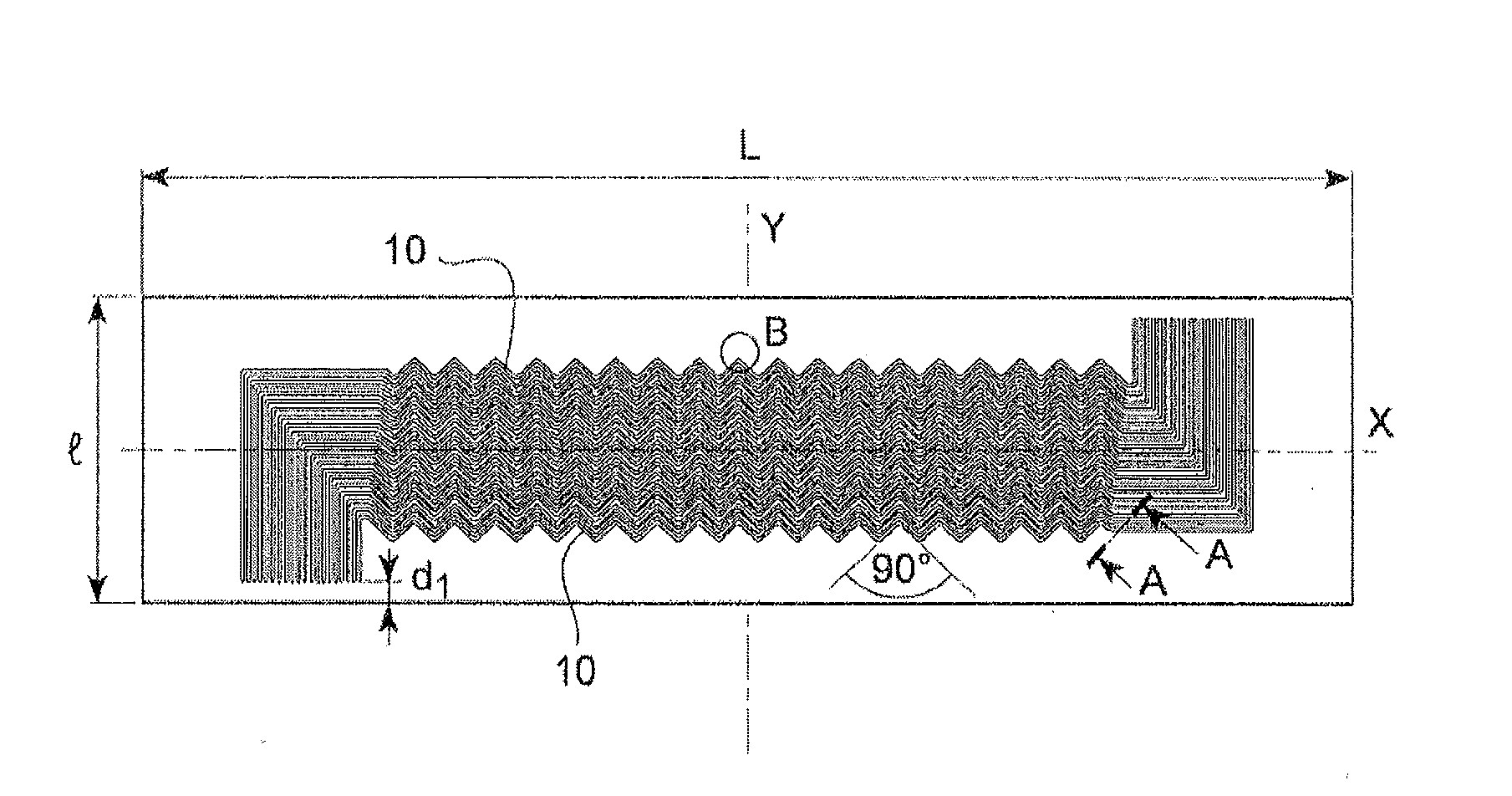
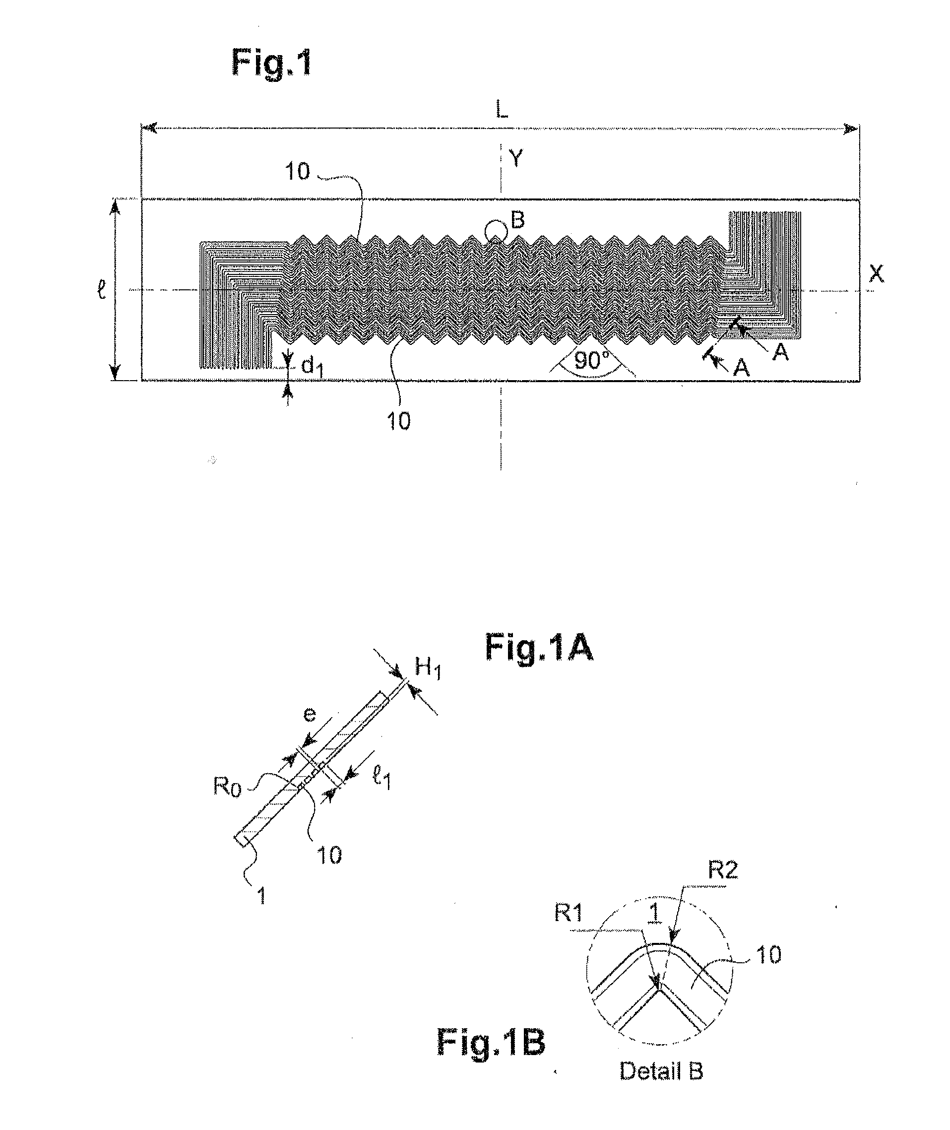
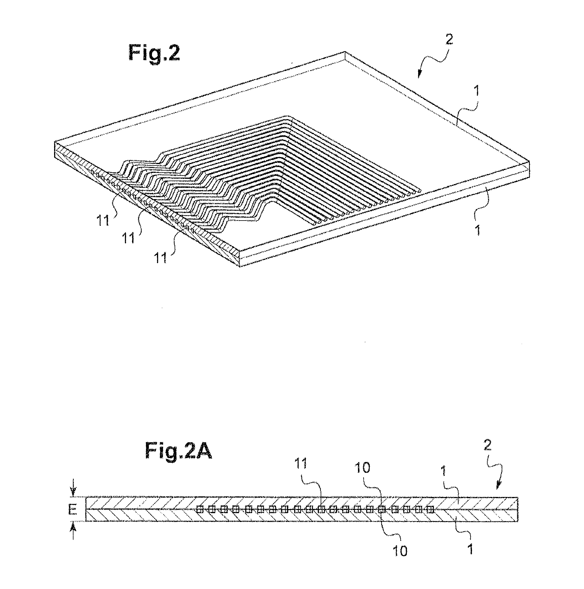
[0092]Step a / : In order to produce an element 2 of a first fluid circuit C1, two mutually identical metal plates 1 are produced having rectangular shapes L*1 and a thickness H, grooves 10 having a depth H1, a width 11 and specific spacing e (FIGS. 1, 1A, 1B). The processing operations of the grooves of the two plates 1 are carried out in accordance with two patterns in a mirror image of each other: as illustrated in FIG. 1, these may advantageously be zig-zag patterns with bends of 90° and inclinations of 45° relative to the longitudinal axis X of the plates 1.

[0093]By way of example, the plates 1 are of stainless steel 1.4404, the dimensions L*1*H of a plate 1 are equal to 602*150*4 mm, the dimensions H1*11 of the grooves are equal to 1*2 mm with tolerances which are equal to ±0.02 mm and ±0.05 mm, respectively, the radii of curvature of the grooves R0, R1, R2 are equal to 0.3 mm, 0.1 mm and 2.1 mm, respectively, the distance e between two consecutive grooves, that is, the...

Example

EXAMPLE 2

[0117]The same steps are carried out as for the example 1, with the difference that, in addition, the main faces of the eleven elements 2 of the first circuit C1 are processed until the wall thickness between the base of the grooves 10 and the exterior is equal to half the desired thickness between each of the two circuits C1, C2.

[0118]A stack 5 is produced by interposing between the eleven elements 2 of the first fluid circuit C1 the twelve elements 30, 4 of the second fluid circuit which have been produced and processed in accordance with the same principle.

[0119]Then, the periphery of the planar faces obtained in this manner is welded, they are degasified and a high-pressure HIP cycle is applied at 1080° C. at 1000 bar for 3 hours.

Example

EXAMPLE 3

[0120]The same steps are carried out as for example 1, with the difference that, in addition, the main faces of the eleven elements 2 of the first circuit C1 are processed until the wall thickness between the base of the grooves 10 and the outer side is equal to half of the desired thickness between each of the two circuits.

[0121]There are ten elements of the second fluid circuit C2 in this instance which are each constituted by a sheet 6 which is itself constituted by square rectified tubes 60 which are arranged parallel with each other and two bars 7 of the same thickness as the tubes, which are added parallel with the tubes at each side of the sheet 6 (FIG. 6). The outer dimensions of a sheet 6, that is, the width and the length, are equal to those of a grooved plate 1 which constitutes an element 2 of the first circuit C1.

[0122]A stack is then produced by interposing between two consecutive elements 2 of the first circuit C1 a sheet 6 of rectified square tubes 60 which ...


PUM

PropertyMeasurementUnit
Temperatureaaaaaaaaaa
Pressureaaaaaaaaaa

Abstract

A method for producing heat exchangers having at least two fluid circuits each having channels, including the following steps: producing one or a plurality of elements of a first fluid circuit, each element having at least two metal plates, at least one of which has first grooves; stacking the at least two metal plates of each element in such a way that the first grooves form the channels of the first circuit; assembling each element of the first circuit by diffusion welding between the two stacked metal plates; producing one or a plurality of elements of at least one second fluid circuit, each element of the second circuit having at least a portion of the channels of the second circuit; assembling, either by diffusion welding, or by brazing, or by diffusion brazing between the element or elements of the first circuit and the element or elements of the second circuit.

Description

TECHNICAL FIELD[0001]The present invention relates to heat exchangers having at least two fluid circuits each comprising channels.[0002]The invention more specifically relates to a new production method for such exchangers by means of diffusion welding obtained by the technique of hot isostatic pressing (HIP).[0003]Known heat exchangers comprise either one or at least two internal fluid circulation channel circuits. In exchangers having a single circuit, the thermal exchanges are carried out between the circuit and a surrounding fluid in which it is immersed. In the exchangers having at least two fluid circuits, the thermal exchanges are carried out between the two fluid circuits.[0004]There are known chemical reactors which implement a continuous method according to which a small quantity of co-reactants are simultaneously injected, at the inlet of a first fluid circuit, preferably provided with a mixer, and the chemical product obtained is recovered at the outlet of the first circ...

Claims


Application Information

Patent Timeline
IPC IPC(8): B23P15/26F28F1/00
CPCF28F1/00B23P15/26B23K20/021B23K2103/04B23K2103/05B23K2103/10B23K2103/12F28D9/0037F28D9/0062F28D9/0075F28D9/0081F28D2021/0054F28F3/048F28F3/12F28F7/02F28F21/083F28F2275/06F28F2275/061
Inventor RIGAL, EMMANUELCACHON, LIONELLEIBOLD, JEAN-MARCMORO-LE GALL, ISABELLEVIDOTTO, FABIEN
Owner COMMISSARIAT A LENERGIE ATOMIQUE ET AUX ENERGIES ALTERNATIVES
Why Eureka
Try Eureka