Optical receiver using wavelength tunable filter

optical receiver technology, applied in the direction of static indicating devices, multiplex communication, instruments, etc., can solve the problems of difficult to manufacture a wavelength tunable filter, difficult to manage optical lines, difficult to adjust the thickness of amorphous silicon, etc., to achieve easy manufacturing and operation of filters, quick wavelength tunable characteristic, and easy to adjust optical lines

Active Publication Date: 2016-04-21
PHOVEL
View PDF17 Cites 20 Cited by
  • Summary
  • Abstract
  • Description
  • Claims
  • Application Information

AI Technical Summary

Benefits of technology

[0030]The wavelength tunable filter applied to an optical receiver according to the present invention is manufactured by very precisely adjusting the thickness of a semiconductor substrate made of silicon for example and then coating a reflective film on both sides of the substrate, so a wavelength is very easily adjusted. That is, when the US patent illustrated in FIG. 1 is applied to four-channel optical communication having a frequency spacing of 200 GHz, at least 600 GHz transmissive frequency should be adjusted, so it is possible to tune any one of four channels to the previous channel by changing the temperature at least by 60° with a transmissive frequency adjusted. However, the wavelength tunable filter according to the present invention can perform tuning to a predetermined channel of other three optical channels by adjusting a transmission frequency by 150 GHz when any one channel is tuned, so it is possible to achieve the same effect as the US patent only by changing tempera ture by 15° C.
[

Problems solved by technology

However, an optical line is not dynamically assigned to the optical receiver that separates specific fixed wavelengths to optical fibers and receives light regardless of the type of the wavelength coupled to specific optical fibers, so it is difficult to manage optical lines.
However, it is very difficult to adjust the thickness of amorphous silicon, so when a wavelength tunable filter is usually manufactured with a difference of several nanometers from a desired wavelength, so it is difficult to manufacture a wavelength tunable filter.
However, when the heater is used, the temperature can be easily increased, but is manually decreased by dissipating he

Method used


Image

  • Optical receiver using wavelength tunable filter
  • Optical receiver using wavelength tunable filter
  • Optical receiver using wavelength tunable filter

Examples


Embodiment Construction

[0063]Preferred embodiments not limiting the present invention will be described hereafter in detail with reference to the accompanying drawings.

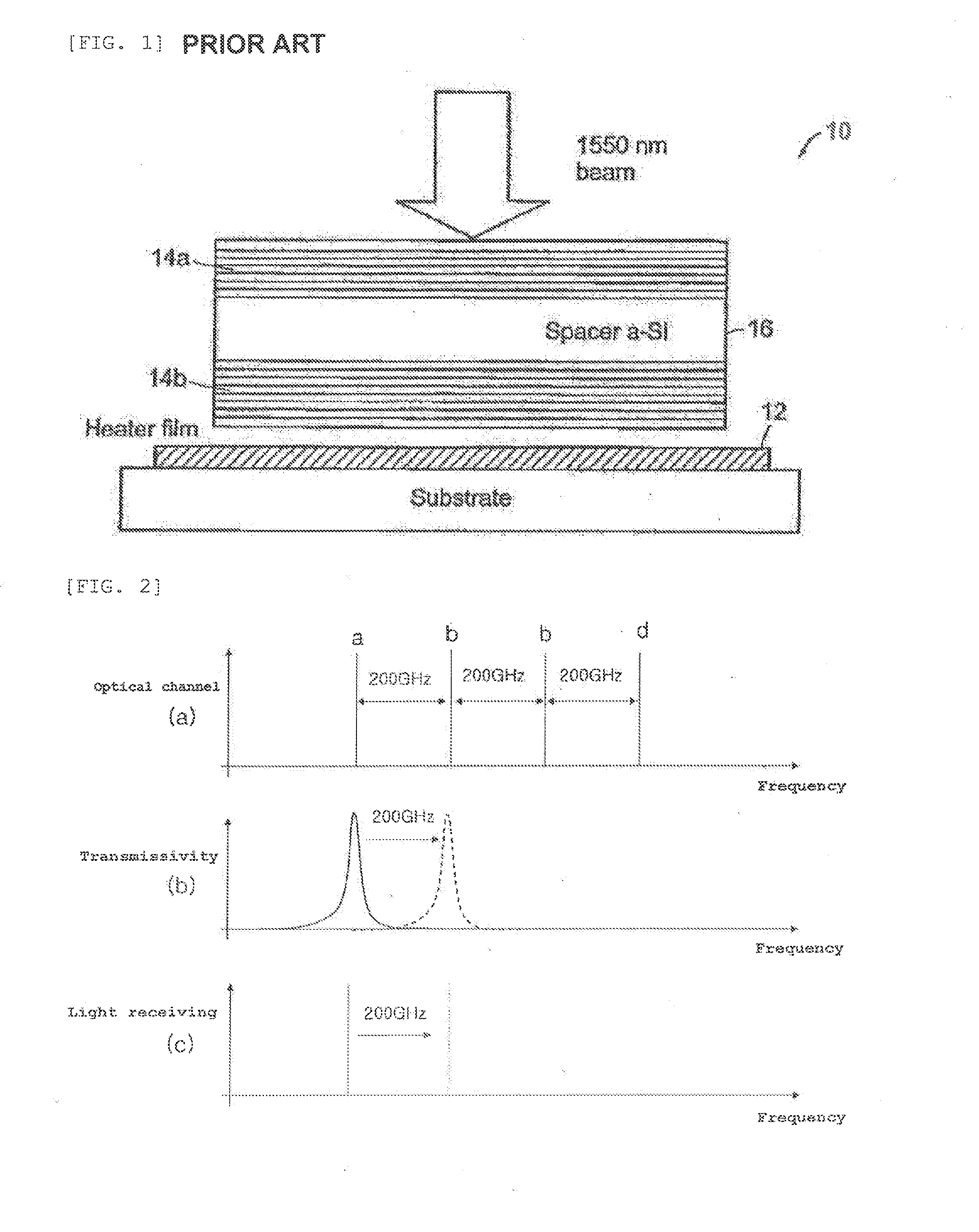
[0064]FIG. 2 is a conceptual diagram illustrating a wavelength tunable characteristic of an optical receiver using a wavelength tunable filter of the related art. In FIG. 2, in order to help understanding the present invention, an optical channel has a four-channel wavelength is used, and the channel frequency spacing is exemplified as 200 GHz, and four optical channels are indicated by a, b, c, and d, respectively.

[0065](a) of FIG. 2 illustrates four optical channels a, b, c, and d arranged with a frequency spacing of 200 GHz. (b) of FIG. 2 exemplifies a transmissive characteristic of an existing wavelength tunable filter, and an optical channel that is selected when the existing wavelength tunable filter transmits the frequency indicated by a solid line (at the left side) is the channel a in (c) of FIG. 2. In this case, an optical channel...


PUM


Abstract

An optical receiver that can tune a selected wavelength using a wavelength tunable filter transmitting a plurality of wavelengths. The optical receiver is a wavelength tunable optical receiver that includes: a wavelength tunable filter (100) transmitting laser light from an optical fiber; and a photodiode (300) receiving laser light passing through the wavelength tunable filter (100), in which the wavelength tunable filter 100 is a Fabry-Perot type etalon filter transmitting a plurality of wavelengths. When a channel with a specific wavelength is moved to a channel with another wavelength, an optical channel is selected based on a peak different from a transmissive peak of an FP etalon filter selecting the previous channel so that temperature of the wavelength tunable filter can be changed. A light-receiving photodiode chip is disposed on a thermoelectric element and a wavelength tunable filter transmits different wavelengths in accordance with temperature of the thermoelectric element.

Description

TECHNICAL FIELD[0001]The present invention relates to an optical receiver using a wavelength tunable filter that can tune a selected wavelength using a wavelength tunable filter transmitting a plurality of wavelengths.BACKGROUND ART[0002]Recently, communication services with large communication capacity, including video service for smart-phones, have been provided. Accordingly, there is a need for greatly increasing the existing communication capacity and a DWDM (Dense Wavelength Division Multiplexing) type communication has been adopted to increase communication capacity using optical fibers that were installed already. The DWDM type communication simultaneously transmits light having several wavelengths through one optical fiber, using a phenomenon that light signals having several wavelengths do not interfere with each other even if they are simultaneously transmitted through one optical fiber, because laser lights having different wavelengths do not interfere with each other.[00...

Claims


Application Information

Patent Timeline
IPC IPC(8): H04Q11/00
CPCH04Q11/0005H04Q2011/0018H04Q2011/0009G02F1/0147H04B10/675G02F1/213G02F1/1345G02F1/13458G02F1/136286G09G3/36G09G3/3648G09G2300/0408G09G2300/0426G09G2320/0209G09G2320/0223H01L27/1218H01L27/124H01L27/1244H01L27/1248G02F1/13629
Inventor KIM, JEONG-SOO
Owner PHOVEL
Why Eureka
Try Eureka