Deposition mask and method for producing deposition mask

a technology of deposition mask and mask, which is applied in the field of deposition mask, can solve the problems of resin film internal stress generation and the inability to form high-quality thin film patterns with high positional accuracy, and achieve the effects of high positional accuracy, reduced positional deviation of opening patterns, and high positional accuracy

Active Publication Date: 2016-04-28
V TECH CO LTD
View PDF0 Cites 32 Cited by
  • Summary
  • Abstract
  • Description
  • Claims
  • Application Information

AI Technical Summary

Benefits of technology

[0013]According to the present invention, the resin film and the metal mask are separated from and independent of each other rather than being brought into tight contact with and fixed to each other unlike the above-mentioned composite mask, and thus the resin film does not have internal stress based on a difference in thermal expansion between the resin film and the metal mask. Accordingly, even when a plurality of opening patterns is formed by laser beam machining, positional deviation of the opening patterns can be reduced, and thus, the opening patterns can be formed with high positional accuracy. Therefore, it is possible to form high definition thin film patterns with high positional accuracy.

Problems solved by technology

However, in the composite mask, a magnetic metal member such as Invar or an Invar alloy, which has a smaller thermal expansion coefficient, and a member such as a resin film, which has a relatively large thermal expansion coefficient, are brought into tight contact with each other at room temperature or higher, and thus internal stress is generated in the resin film due to a difference in thermal expansion between both the members.
Therefore, there is a concern that high definition thin film patterns cannot be formed with high positional accuracy.

Method used


Image

  • Deposition mask and method for producing deposition mask
  • Deposition mask and method for producing deposition mask
  • Deposition mask and method for producing deposition mask

Examples


Embodiment Construction

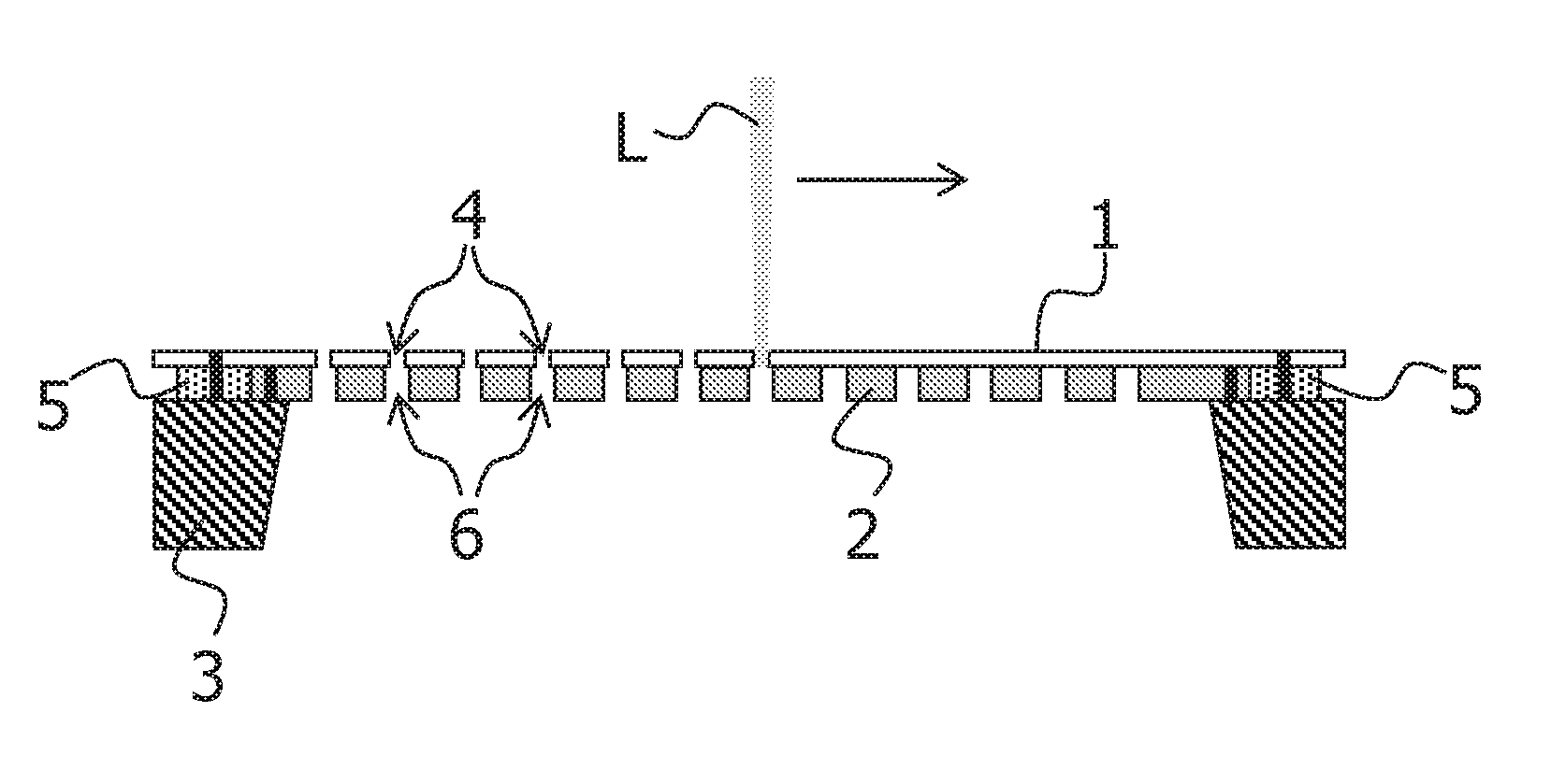
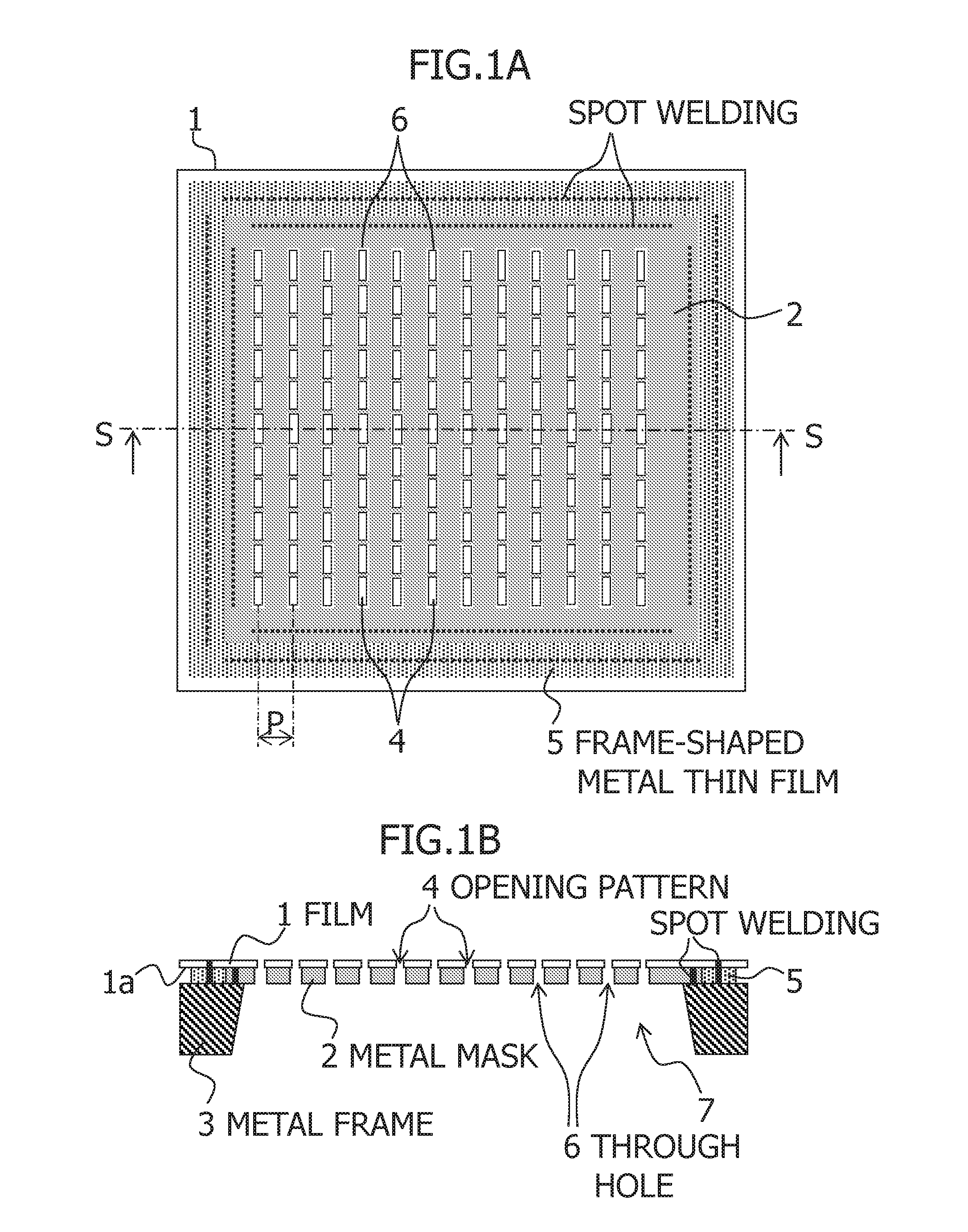
[0024]Hereinafter, embodiments of the present invention will be described in detail with reference to the accompanying drawings. FIGS. 1A and 1B are diagrams illustrating a deposition mask according to a first embodiment of the present invention. FIG. 1A is a plan view, and FIG. 1B is a diagram taken along with a line S-S of FIG. 1A when seen from an arrow. The deposition mask is provided with a plurality of opening patterns corresponding to a plurality of thin film patterns to be deposited on a substrate, and is configured to include a resin film 1, a metal mask 2, and a metal frame 3.

[0025]The film 1 is a resin film provided with a plurality of penetrating opening patterns 4 formed therein so as to correspond to the plurality of thin film patterns to be deposited on the substrate, each opening pattern 4 having the same shape and dimensions as those of the corresponding thin film pattern, and the film 1 is, for example, a resin film made of a resin that transmits visible light, suc...


PUM

PropertyMeasurementUnit
thicknessaaaaaaaaaa
thicknessaaaaaaaaaa
thicknessaaaaaaaaaa

Abstract

A deposition mask is provided. The deposition mask including: a resin film 1 in which penetrating opening patterns 4 are formed and a frame-shaped metal thin film 5 having an opening is provided on one face 1a of the film 1; a metal mask 2 provided at a position corresponding to the opening of the metal thin film 5 on one face 1a side of the film 1, the metal mask 2 being separated from and independent of the film 1, the metal mask 2 being provided with through holes 6; and a metal frame 3 positioned on one face 1a side of the film 1, the metal frame 3 supporting the film 1 and the metal mask 2 by spot-welding a portion of the metal thin film 5 and an edge region of the metal mask 2 to one end face 3a.

Description

[0001]This application is a continuation application of PCT / JP2014 / 067332, filed on Jun. 30, 2014, which is hereby incorporated by reference in its entirety for all purposes.BACKGROUND OF THE INVENTION[0002]1. Field of the Invention[0003]The present invention relates to a deposition mask provided with a plurality of opening patterns corresponding to a plurality of thin film patterns to be deposited on a substrate, and more particularly, relates to a deposition mask capable of forming high definition thin film patterns with high positional accuracy, and a method of manufacturing the deposition mask.[0004]2. Description of Related Art[0005]A conventional deposition mask is a metal mask provided with a plurality of penetrating opening patterns corresponding to a plurality of thin film patterns to be deposited on a substrate. The mask is manufactured as follows: a first resist pattern having a plurality of through openings is formed on a metal plate, an etching process is performed thro...

Claims


Application Information

Patent Timeline
Patent Type & Authority Applications(United States)
IPC IPC(8): C23C14/04B23K11/11B23K26/382C23C16/04
CPCC23C14/042B23K26/382B23K11/11C23C16/042C23F1/02H10K71/166
Inventor MIZUMURA, MICHINOBU
Owner V TECH CO LTD
Why Eureka
Try Eureka