Magneto-impedance sensor element with electromagnetic coil and magneto-impedance sensor with electromagnetic coil

a technology of magnetoimpedance sensor and electromagnetic coil, which is applied in the direction of magnetic measurement, instruments, measurement devices, etc., can solve the problems of insufficient miniaturization, and insufficient sensitivity and accuracy for dynamic 3-dimensional compasses, etc., to achieve easy to achieve finely pitched coils, increase coil aspect ratio, and high sensitivity

Inactive Publication Date: 2016-04-28
MAGNE DESIGN
View PDF6 Cites 7 Cited by
  • Summary
  • Abstract
  • Description
  • Claims
  • Application Information

AI Technical Summary

Benefits of technology

[0032]The magneto-impedance sensor element with electromagnetic coil according to the first aspect of the present invention has features that the coil formed to be wound around the magnetic sensitive body above the electrode wiring substrate has a three-layer structure comprising: coil lower portions of a recessed shape; coil upper portions of a protruding shape; and joint portions that joint the coil lower portions and the coil upper portions and that the coil is isolated from the magnetic wire by an insulating material. According to the features, an increased coil aspect ratio and a finely pitched coil can readily be achieved. Consequently, when the element of the present invention is combined with a sample and hold circuit with buffer circuit, or when the direct connection of the MI element with an integrated circuit using solder is further combined therewith, effects are obtained that the MI sensor can have high sensitivity, low noise, and expanded measurement range, and can be miniaturized.
[0033]The magneto-impedance sensor element with electromagnetic coil according to the second aspect of the present invention has a feature of employing a magnetic wire covered with an insulating material in addition to the features of the first aspect of the present invention. According to the feature, spaces between the coil lower portions of a recessed shape and the coil upper portions of a protruding shape can be further reduced thereby to further reduce the coil pitch.
[0034]The magneto-impedance sensor element with electromagnetic coil according to the third aspect of the present invention has features that the length is 0.30 mm or less and the number of coil turns is 20 or more.

Problems solved by technology

However, while magnetic sensors for electronic compasses using conventional MI-elements have achieved sufficient performance as 3-dimensional compasses

Method used


Image

  • Magneto-impedance sensor element with electromagnetic coil and magneto-impedance sensor with electromagnetic coil
  • Magneto-impedance sensor element with electromagnetic coil and magneto-impedance sensor with electromagnetic coil
  • Magneto-impedance sensor element with electromagnetic coil and magneto-impedance sensor with electromagnetic coil

Examples


first embodiment

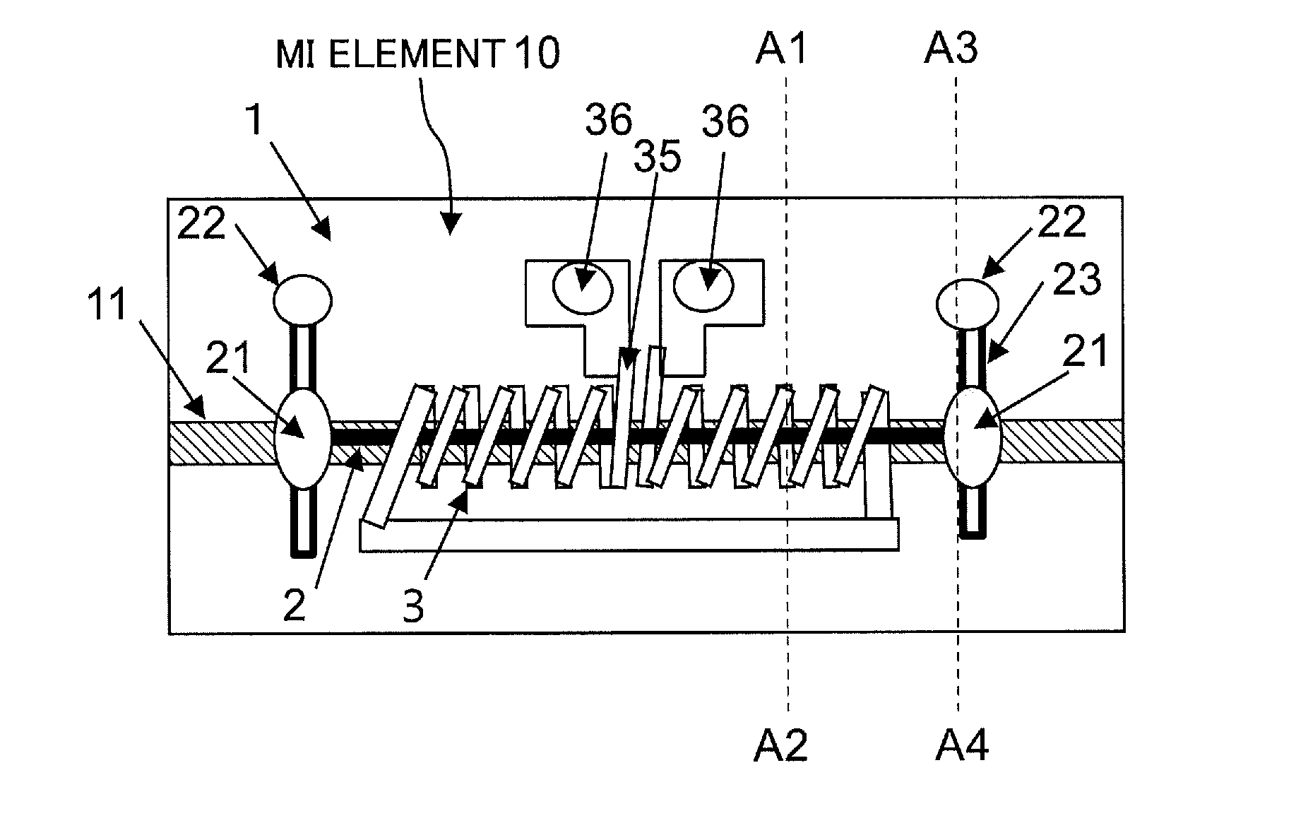
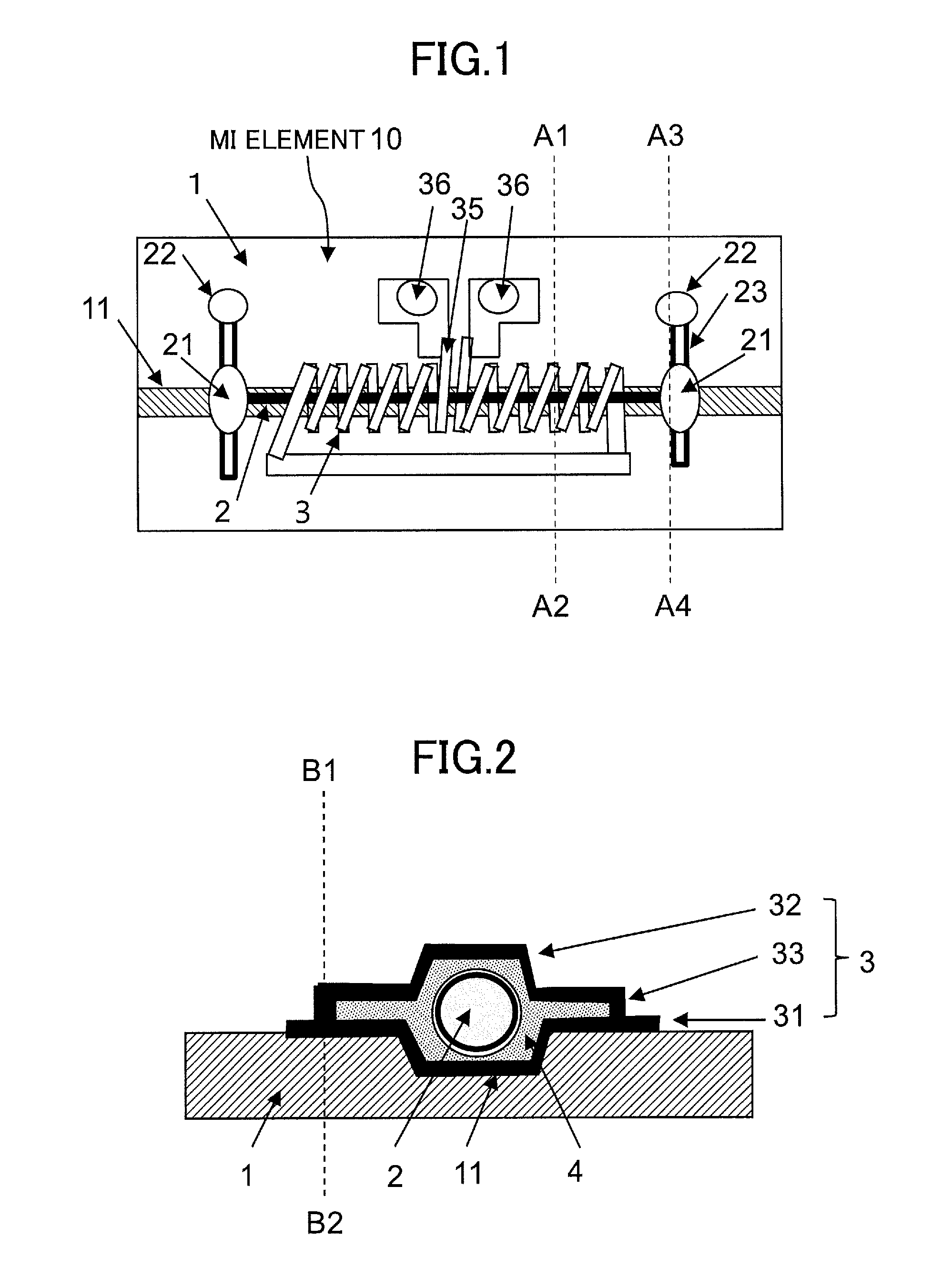
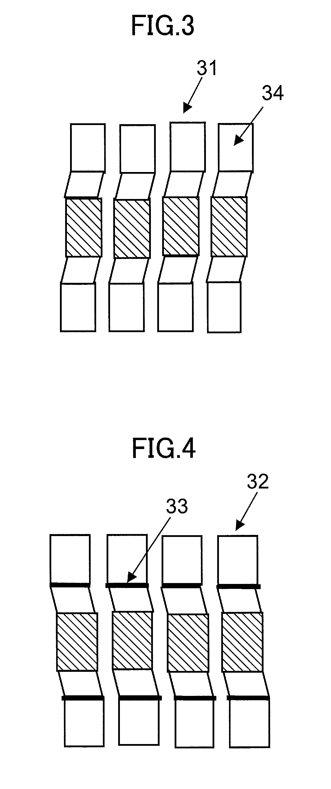
[0047]The magneto-impedance sensor element with electromagnetic coil of the first embodiment will be described with reference to an MI element shown in FIG. 1 and FIG. 2. In the MI element, an amorphous magnetic wire 2 of Co alloy for detecting a magnetic field is located above an electrode wiring substrate 1 so that the magnetic wire 2 is supported via an insulator 4 by an electromagnetic coil 3 of a three-layer structure, i.e., an electromagnetic coil 3 that has a structure comprising: coil lower portions 31 of a recessed shape; coil upper portions 32 of a protruding shape; and joint portions 33 that joint the coil lower portions 31 and the coil upper portions 32. The electromagnetic coil 3 has a coil pitch of 14 micrometers or less, an inner diameter of 40 micrometers or less, and a coil aspect ratio of 2 or more. Terminals of the wire 2 and electromagnetic coil 3 are connected to respective electrodes 22 and 36 on the electrode wiring substrate 1, and solder balls are disposed o...

second embodiment

[0056]The second embodiment relates to an MI sensor in which the MI element of the first embodiment and a sample and hold circuit with buffer circuit are used in combination. In a fine-pitch coil, when the coil separation is reduced to half to double the number of coil turns, the cross-sectional area of the coil strips may have to be half if the coil strip thickness is the same, and the coil length is doubled. This results in the electrical resistance quadrupled. If the coil output voltage is directly sampled and held via an electrical switch, a current flows in the coil to quadruple the voltage drop, which significantly reduce the measurement value of the coil output voltage. Therefore, the present embodiment employs a circuit that samples and holds the output voltage via a buffer circuit and an electrical switch, thereby to provide an MI sensor which can suppress the voltage drop to obtain an output voltage proportional to the number of coil turns.

example 1

[0057]Hereinafter, examples of the present invention will be described with reference to the drawings.

[0058]The magneto-impedance sensor element with electromagnetic coil of the first example will now be described with reference to FIG. 1 and FIG. 2.

[0059]The electrode wiring substrate 1 has a size of a length of 0.3 mm, a width of 0.2 mm, and a height of 0.2 mm. The magnetic sensitive body is an amorphous wire 2 of CoFeSiB-based alloy having a diameter of 10 micrometers and covered with glass. The coil lower portions 31 of a recessed-shape on the substrate 1 have a depth of 7 micrometers, a strip width of 2 micrometers, a coil width of 40 micrometers, and a thickness of 1 micrometer. The joint portions 33 have a height of 1 micrometer and a thickness of 1 micrometer. The coil upper portions 32 of a protruding shape have a height of 7 micrometers, a strip width of 2 micrometers, a coil width of 40 micrometers, and a thickness of 1 micrometer. The electromagnetic coil 3 has a three-l...


PUM


Abstract

A technique is provided which reduces the coil pitch and increases the number of coil turns in an MI element and allows for high sensitivity and miniaturization. The MI element is configured such that a magnetic wire and a coil wound around the magnetic wire are disposed on an electrode wiring substrate. When manufacturing the coil, a three-layer structure of the coil and thin film coil strips formed by a vapor deposition process are focused on thereby to allow the coil pitch to be 14 micrometers or less. The three-layer structure comprises coil lower portions of a recessed shape, coil upper portions of a protruding shape, and through-hole portions that connect the coil lower portions with the coil upper portions.

Description

TECHNICAL FIELD[0001]The present invention relates to a technique for reducing the coil pitch and increasing the number of coil turns in a magneto-impedance sensor element (referred to as an “MI element” hereinafter), which uses an electromagnetic coil and is used as a magnetic sensor, thereby to miniaturize the MI element while enhancing the sensitivity or maintaining the sensitivity.BACKGROUND ART[0002]Electronic compasses using MI elements are currently used as 3-dimensional compasses for various purposes, such as for smartphones and motion capture. In the future, such electronic compasses are expected as dynamic 3-dimensional compasses and accordingly required to have more enhanced performance. However, while magnetic sensors for electronic compasses using conventional MI-elements have achieved sufficient performance as 3-dimensional compasses, a problem is that enhanced sensitivity and accuracy and miniaturization are insufficient for dynamic 3-dimensional compasses which the m...

Claims


Application Information

Patent Timeline
IPC IPC(8): G01R33/06
CPCG01R33/063
Inventor HONKURA, YOSHINOBU
Owner MAGNE DESIGN
Why Eureka
Try Eureka