Optical element, electro-optical device, and mounted display apparatus

a technology of electrooptical devices and optical elements, applied in the direction of optics, instruments, diffraction gratings, etc., can solve the problems of difficulty in sufficiently enlarging the image light in the abovementioned optical elements, and achieve excellent usability, high display quality, and high reliability

Active Publication Date: 2016-05-05
SEIKO EPSON CORP
View PDF7 Cites 37 Cited by
  • Summary
  • Abstract
  • Description
  • Claims
  • Application Information

AI Technical Summary

Benefits of technology

[0029]In this case, since it is possible to mount the abovementioned electro-optical device, adjustment that exactly matches a position of image light to a position of a pupil is unnecessary, and therefore, it is possible to provide a mounted display apparatus with high display quality, high reliability and excellent usability.

Problems solved by technology

In such head mounted display, adjustment that exactly matches a display position of an image to a position of a pupil becomes necessary if images are smaller than a pupil diameter, and therefore, since usability is worsened, optical elements that enlarge image light beyond the pupil diameter are used.
However, in a method that scans using a fine laser beam, since the image light becomes considerably small in comparison with pupil diameter, it is difficult to sufficiently enlarge the image light in the abovementioned optical elements.

Method used


Image

  • Optical element, electro-optical device, and mounted display apparatus
  • Optical element, electro-optical device, and mounted display apparatus
  • Optical element, electro-optical device, and mounted display apparatus

Examples


embodiment 1

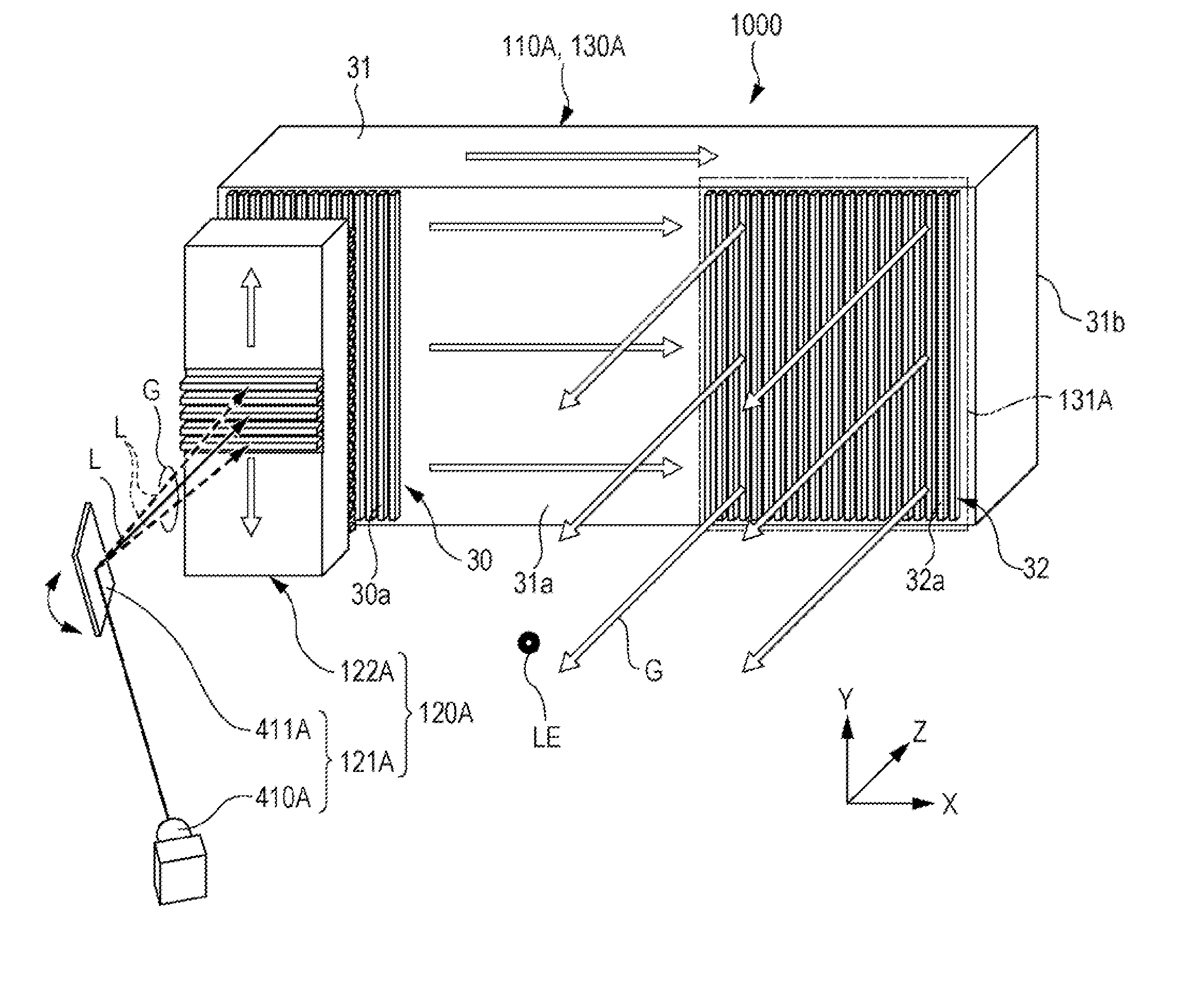
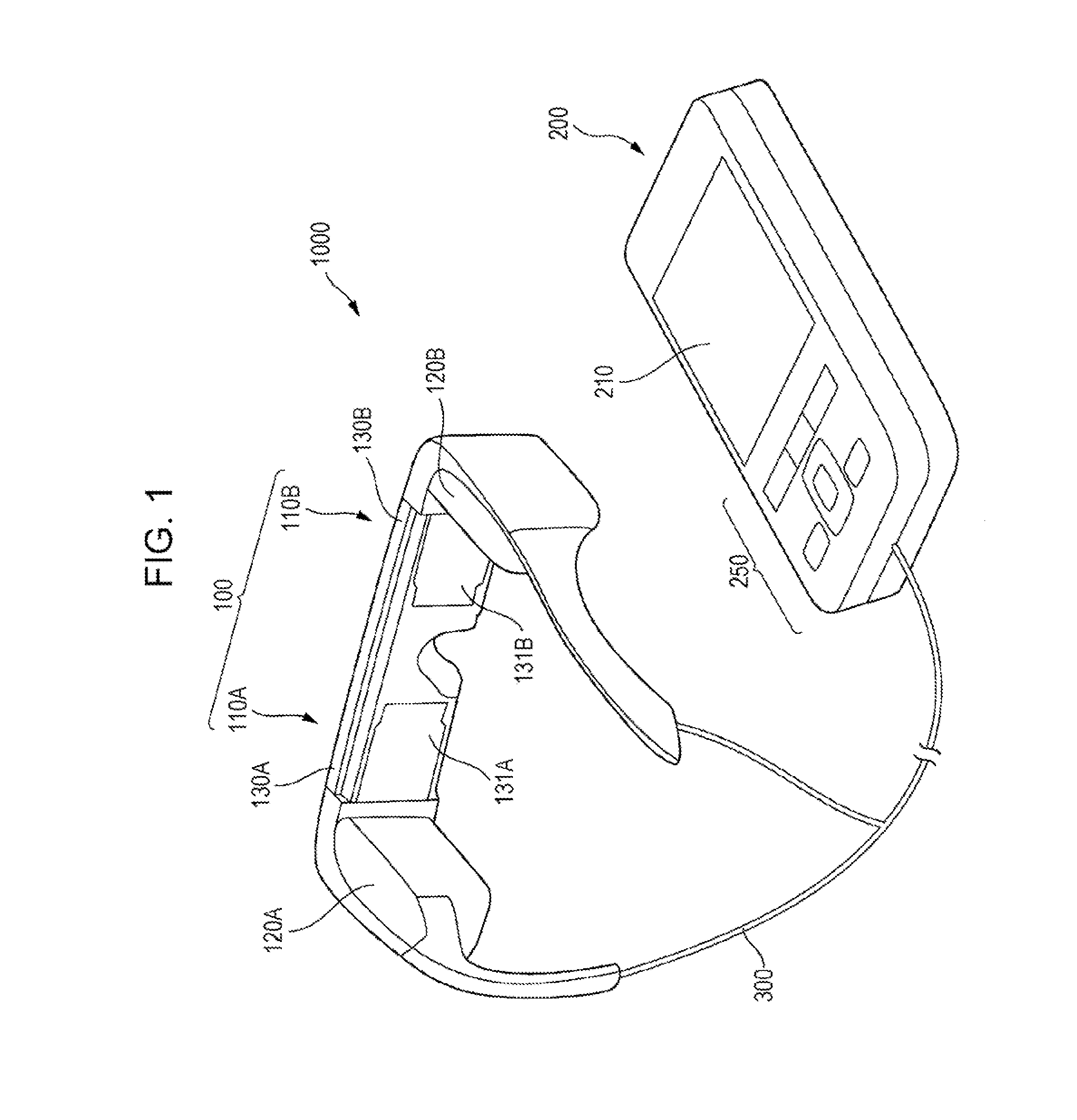
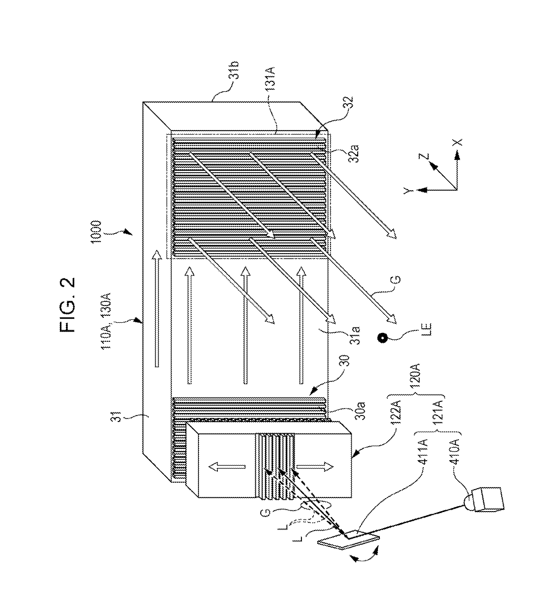
[0042]FIG. 1 is an external view of an electro-optical device according to the present embodiment. In the present embodiment, a transmission type head mounted display (a mounted display apparatus 1000) is shown as the electro-optical device. The mounted display apparatus 1000 includes an optical element, which is an aspect of the invention. In the following description, head mounted display is abbreviated to HMD.

[0043]The mounted display apparatus 1000 according to the present embodiment is a see-through type (transmission type head mounted display) HMD, which is provided with a main body section (a mounting section) 100 that has a glasses-type shape, and a control unit 200 that has a size of an extent that is capable of being held in a users hand. According to the mounted display apparatus 1000 of the present embodiment, it is possible for a user to view images that are created by an image display section, and it is also possible to for the user to view external scenery.

[0044]The m...

second embodiment

[0118]Next, an optical element according to a second embodiment of the invention will be described. The present embodiment includes a feature in a manufacturing method of an optical element. Additionally, the same names are given to the same structures as the first embodiment, and detailed description thereof is omitted.

[0119]FIG. 7 is a view that shows a cross-sectional configuration of an optical element 150 according to a second embodiment.

[0120]As shown in FIG. 7, an optical element 150 of the present embodiment includes a transparent substrate (a light guide body) 51, a first diffraction section 54, a second diffraction section 55, a half mirror 53, a mirror 52, a first base section 54A, and a second base section (a resin layer) 55A.

[0121]In the present embodiment, a glass substrate in which the parallelization of both surfaces is ensured are used as the transparent substrate 51.

[0122]The first diffraction section 54 and the second diffraction section 55 are, for example, confi...

third embodiment

[0139]Next, an optical element according to the third embodiment of the invention will be described. The difference between the present embodiment and the first embodiment is the optical characteristics of the half mirror 23, and other configurations are common to both embodiments. Therefore, the description below will be given focusing on the optical characteristics of the half mirror 23.

[0140]FIGS. 9A and 9B are views that show optical characteristics of a half mirror of the present embodiment, FIG. 9A is a graph that shows changes in the reflectance of the half mirror, and FIG. 9B is a graph that shows the intensity of image light that is emitted from the second diffraction section 22. Additionally, in FIG. 9B, the light intensity of laser light that is emitted to the outside is shown within a range of ±15 mm with respect to the center (Y=0) of the half mirror. In addition, in FIG. 9B, each light intensity of the blue laser light LB, the red laser light LR and the green laser lig...


PUM


Abstract

An optical element includes a light guide is provided with a incidence section and a emission section, a semitransmissive reflective film is provided in the inside of the light guide, a first diffraction element is provided in the incidence section, and is provided with a plurality of gratings, a second diffraction element is provided in the emission section, and is provided with a plurality of gratings, and a reflective film is provided in the incidence section in a periphery of the first diffraction element, in which the pitch of the plurality of gratings of the first diffraction element is equivalent to the pitch of the plurality of gratings of the second diffraction element, and each extension direction of the plurality of gratings of the first diffraction element is the same direction as each extension direction of the plurality of gratings of the second diffraction element.

Description

BACKGROUND[0001]1. Technical Field[0002]The present invention relates to an optical element, an electro-optical device, and a mounted display apparatus.[0003]2. Related Art[0004]In recent years, mounted display apparatus such as head mounted displays have attracted attention. In such head mounted display, adjustment that exactly matches a display position of an image to a position of a pupil becomes necessary if images are smaller than a pupil diameter, and therefore, since usability is worsened, optical elements that enlarge image light beyond the pupil diameter are used. As such an optical element, a technology that enlarges image light by using two diffraction gratings, is known (for example, refer to JP-A-07-72422).[0005]Incidentally, miniaturization is highly regarded in head mounted displays, and the miniaturization of devices has been realized by drawing images on the retina of the eye by scanning with a laser beam. In such an instance, the combined use of the abovementioned ...

Claims


Application Information

Patent Timeline
Patent Type & Authority Applications(United States)
IPC IPC(8): G02B27/01G02B27/42G02B6/34
CPCG02B27/0172G02B6/34G02B2027/0178G02B27/4205G02B2027/0123G02B27/4272G02B6/005
Inventor YOKOYAMA, OSAMU
Owner SEIKO EPSON CORP
Why Eureka
Try Eureka