System and method for locating, measuring, counting, and aiding in the handling of drill pipes

a technology for locating, measuring, counting, and drilling pipes, which is applied in the direction of image enhancement, survey, and borehole/well accessories. it can solve the problems of significant disruption to drilling activities, significant disruption of drilling activities, and difficulty in measuring a large portion of rig activities and sensing problems, so as to reduce the risk of pipe tally errors, save drilling time and cost, and more accurate technique for generating

Active Publication Date: 2016-05-12
HELMERICH & PAYNE TECH LLC
View PDF4 Cites 15 Cited by
  • Summary
  • Abstract
  • Description
  • Claims
  • Application Information

AI Technical Summary

Benefits of technology

[0004]By applying automated, computer-based video interpretation, continuous, robust, and accurate assessment of many different phenomena can be achieved through pre-existing video data without requiring a person-in-the-loop. Automated interpretation of video data is known as computer vision, and recent advances in computer vision technologies have led to significantly improved performance across a wide range of video-based sensing tasks. Computer vision can be used to improve safety, reduce costs and improve efficiency.
[0006]Classical instrumentation for pipe tallying is either time-consuming (e.g., manual measurement of each pipe) or not suitable for harsh down-well conditions (e.g., RFID tagging). In contrast, computer vision technologies can be utilized to perform many of the activities currently undertaken manually, providing significant savings in drilling time and cost and reducing the risk from pipe tally errors. These techniques provide a more accurate technique for generating pipe tallies and can significantly reduce rig down-time due to pipe tally errors; potentially saving millions of dollars per year. Therefore, there is a need for an automated computer vision based technique for measuring pipe lengths and diameters, and counting pipe segments as they enter into or are removed from the well-bore.

Problems solved by technology

Despite the multitude of sensors on today's rigs, a significant portion of rig activities and sensing problems remain difficult to measure with classical instrumentation and person-in-the-loop sensing is often utilized in place of automated sensing.
Although a relatively simple human endeavor, errors in pipe tallying can and do occur, and these errors can cause significant disruptions to drilling activities.
Classical instrumentation for pipe tallying is either time-consuming (e.g., manual measurement of each pipe) or not suitable for harsh down-well conditions (e.g., RFID tagging).

Method used


Image

  • System and method for locating, measuring, counting, and aiding in the handling of drill pipes
  • System and method for locating, measuring, counting, and aiding in the handling of drill pipes
  • System and method for locating, measuring, counting, and aiding in the handling of drill pipes

Examples


Embodiment Construction

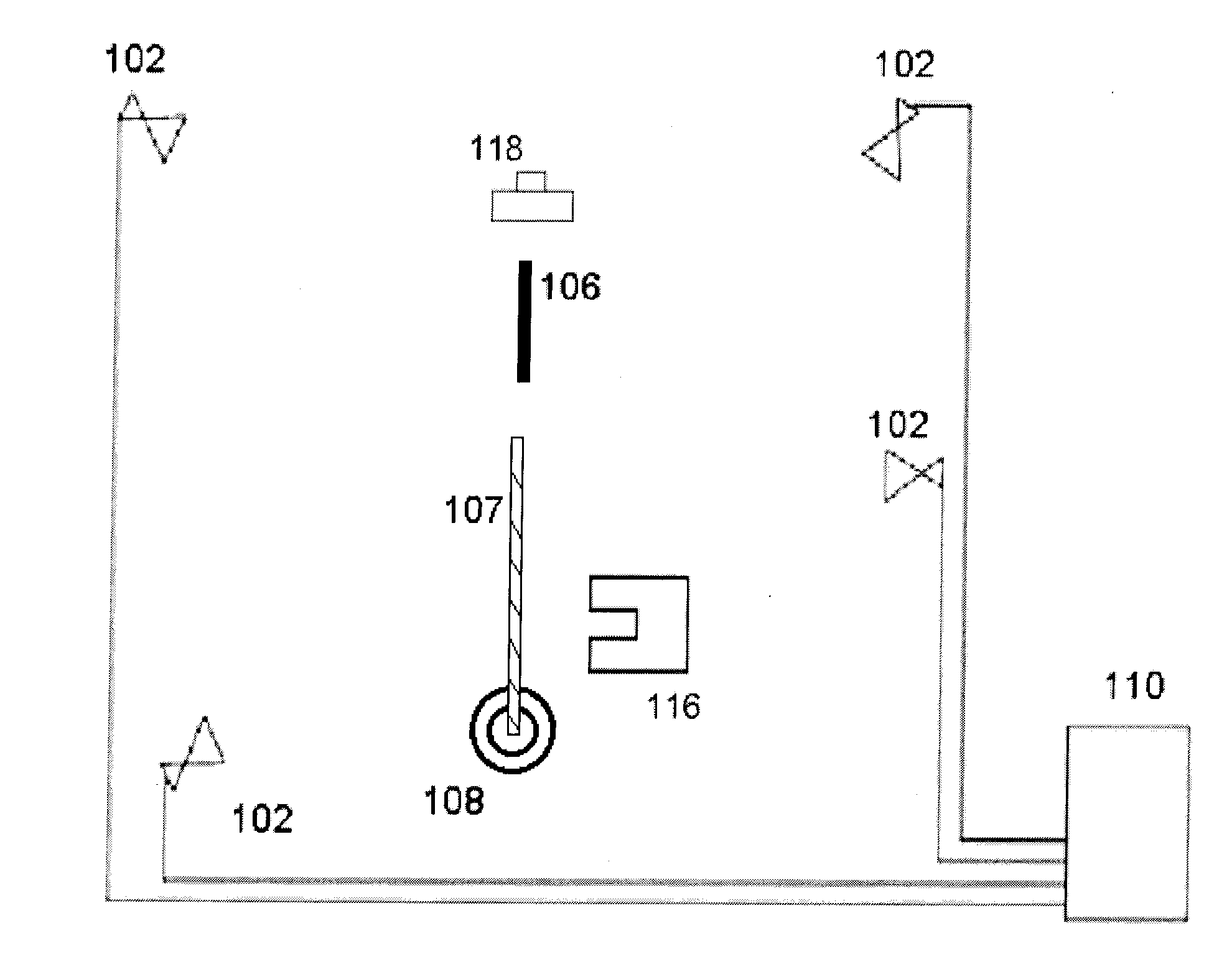
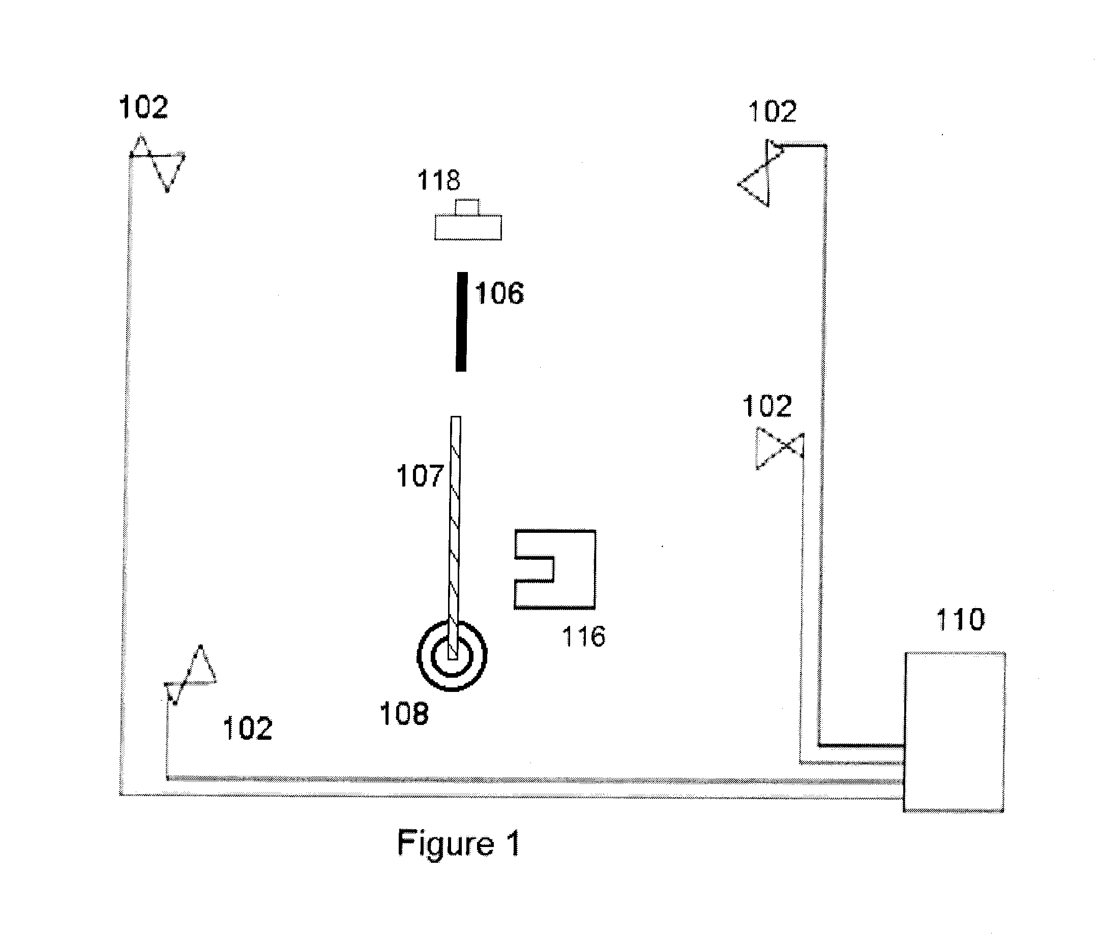
[0010]The “Pipe Tally System” system, PTS, consists of several parts. In one preferred embodiment, one or more video cameras 102 positioned so as to be able to see the drilling pipe 106 as it is attached to, or removed from the drill-string 107. Depending on requirements, one camera 102 at sufficient distance from the bore-hole 108 to view the entire pipe 106 segment at once may be sufficient, otherwise two or more cameras 102 may be used, each of which may only see part of the pipe 106 as it is entered into the drill-string 107, but information or data 150 can be aggregated across the different cameras using the known camera positions and poses.

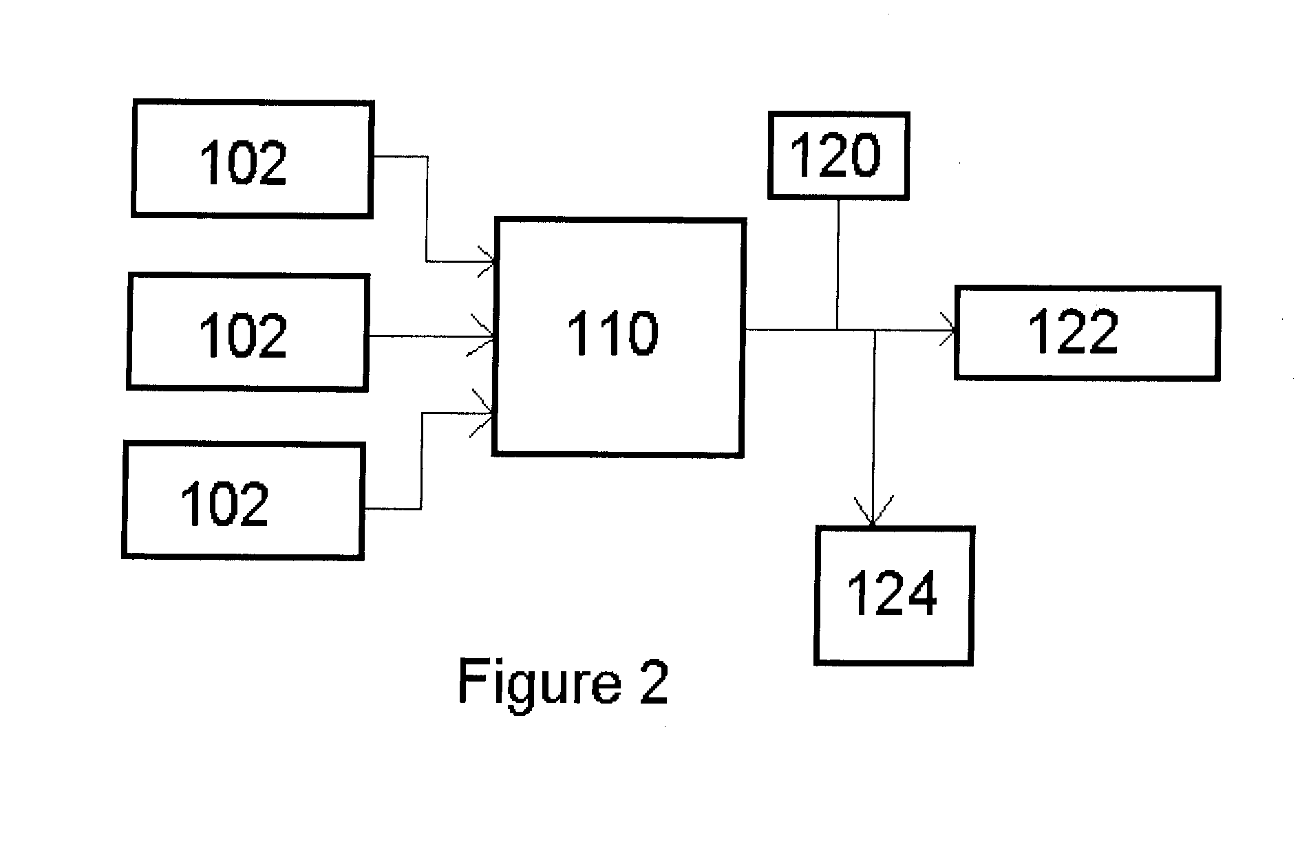
[0011]Each camera 102 may contain or be connected to a computer 110 which detects and localizes pipes 106, the iron roughneck 116, the elevator 118, or other relevant components. Different regions of interest for each object type can be defined using the known camera 102 geometry, or using user-inputs. Since the cameras 102 are at known dist...


PUM


Abstract

Disclosed embodiments relate to systems and methods for locating, measuring, counting or aiding in the handling of drill pipes 106. The system 100 comprises at least one camera 102 capable of gathering visual data 150 regarding detecting, localizing or both, pipes 106, roughnecks 116, elevators 118 and combinations thereof. The system 100 further comprises a processor 110 and a logging system 114 for recording the gathered visual data 150. The method 200 comprises acquiring visual data 150 using a camera 106, analyzing the acquired data 150, and recording the acquired data 150.

Description

FIELD OF THE INVENTION[0001]Embodiments described herein relate to systems and methods for locating, measuring, counting, and aiding in the handling of drill pipes.BACKGROUND AND SUMMARY[0002]Modern drilling involves scores of people and multiple inter-connecting activities. Obtaining real-time information about ongoing operations is of paramount importance for safe, efficient drilling. As a result, modern rigs often have thousands of sensors actively measuring numerous parameters related to vessel operation, in addition to information about the down-hole drilling environment.[0003]Despite the multitude of sensors on today's rigs, a significant portion of rig activities and sensing problems remain difficult to measure with classical instrumentation and person-in-the-loop sensing is often utilized in place of automated sensing.[0004]By applying automated, computer-based video interpretation, continuous, robust, and accurate assessment of many different phenomena can be achieved throu...

Claims


Application Information

Patent Timeline
Patent Type & Authority Applications(United States)
IPC IPC(8): E21B19/06H04N7/18G01B11/08G06T7/00G01B11/02E21B41/00H04N5/225
CPCE21B19/06E21B41/0092H04N7/181H04N5/225G06T2207/30108G06T7/0004G01B11/02G01B11/08G06T7/0081E21B41/00E21B44/00E21B47/04E21B19/20E21B17/006G01B11/022G08B21/182G08B21/187
Inventor TORRIONE, PETER A.
Owner HELMERICH & PAYNE TECH LLC
Why Eureka
Try Eureka