Multi-injection port rotary engine apparatus and method of use thereof

Inactive Publication Date: 2016-05-12
PEKRUL MERTON W
View PDF2 Cites 15 Cited by
  • Summary
  • Abstract
  • Description
  • Claims
  • Application Information

AI Technical Summary

Benefits of technology

[0027]The invention comprises a rotary engine apparatus and method of use ther

Problems solved by technology

All internal combustion engines suffer from poor efficiency; only a small percentage of the potential energy is released during combustion as the combustion is invariably incomplete.
Even with the support system, a significant quantity of pollutants is released into the atmosphere as a result of incomplete combustion when using an internal combustion engine.
Because internal combustion engines depend upon the rapid and explosive combustion of fuel within the engine itself, the engine must be engineered to withstand a considerable amount of heat and pressure.
These are drawbacks that require a more robust and more complex engine over external combustion engines of similar power output.
The high rotational speeds present several engineering challenges that typically

Method used


Image

  • Multi-injection port rotary engine apparatus and method of use thereof
  • Multi-injection port rotary engine apparatus and method of use thereof
  • Multi-injection port rotary engine apparatus and method of use thereof

Examples


example v

[0277]In another example, a rotary engine having a housing, a rotor, and a set of vanes is used where the set of vanes divides a volume between the rotor and the housing into a set of chambers. A stressed sheet, such as the stressed band 3410, in a first vane of the set of vanes, is used to apply a radially outward force on a section of the first vane toward said housing. Further, electromechanical means for controlling extension of the first vane toward said housing and / or away from the housing are used. Preferable, the electromechanical means: (1) extend the stressed sheet toward the housing when an operational speed, or rotation rate, of the engine decreases and / or (2) retract the stressed sheet away from the housing when the operational speed of the engine increases. Optionally, the stressed sheet yields: (1) a first force on the first vane toward the rotor at a first engine speed and (2) a second force on the first vane toward the rotor housing at a second engine speed, where t...

example vi

[0278]In another example, the stressed sheet, described supra, rolls into the spooler 3436. For example, the spooler optionally contains two outer ends and a curved connecting surface, such as a spool of thread. The spooler optionally contains a slit, through which the stressed sheet passes and an interior surface about which the stress sheet spools. The outer curved connecting surface thus comprises a barrier against which the stressed sheet pushes, where the force is transferred by mechanical means to the vane, such as with the follower.

Vane Cam

[0279]In another embodiment, one or more sealing forces applied to the vane 450 toward the housing 210 are non-linear with rotation of the rotary engine 110. An example of a non-linear force is provided, infra.

[0280]Referring now to FIG. 39, a non-linear cam roller 3920 used in actuation of the vane 450 is described. Generally, rotational motion of the cam roller 3920, which is an example of the spooler 3436, is transferred to linear motion...

example i

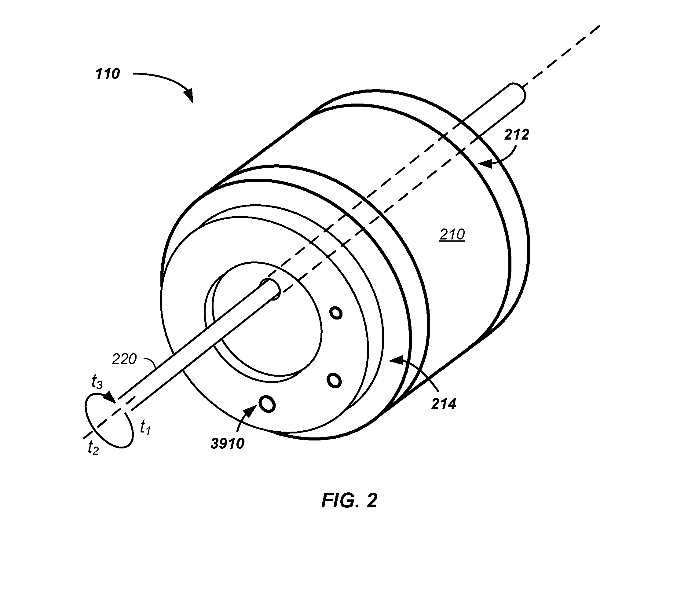
[0291]Referring again to FIG. 2 and FIG. 3 and still referring to FIG. 39, in a first example, fuel is injected via multiple injection ports of the set of inlet ports 3910, such as via: (1) a first injection port 3912 into the first expansion chamber 335; (2) a second injection port 3914 into the second expansion chamber 345; and / or (3) a third injection port into the third expansion chamber 355. The injected fuel is optionally a cryogenic fuel and / or a liquid phase fuel that is a gas at room temperature, such as a liquid carbon dioxide or liquid nitrogen fuel, that rapidly expands in the warmer expansion chambers resulting in expansion forces. In addition to rotating the rotor 440 and vane 450, the expansion forces provide an additional sealing force, FSA. Optionally, the first injection port 3912, the second injection port 3914, and third injection port are of different diameters and / or deliver different amounts of fuel. For instance, the second injection port optionally delivers ...


PUM


Abstract

The invention comprises a rotary engine apparatus and method of use thereof, where the rotary engine comprises multiple injection ports. Optional injection ports include a first port in an expansion chamber, a second port in the expansion chamber after a first rotation of the rotor, a third port into the expansion chamber after a second rotation of the rotor, a fourth port from a fuel path through a shaft of the rotary engine, and/or a fifth port into a rotor-vane chamber between the rotor and a vane. Optionally, one or more of the injection ports are controlled through mechanical valving and/or through electronic and/or computer control.

Description

CROSS-REFERENCES TO RELATED APPLICATIONS[0001]This application is a continuation-in-part of U.S. patent application Ser. No. 14 / 821,682 filed Aug. 7, 2015, which[0002]claims benefit of U.S. provisional patent application No. 62 / 035,461 filed Aug. 10, 2014;[0003]claims benefit of U.S. provisional patent application No. 62 / 038,116 filed Aug. 15, 2014; and[0004]claims benefit of U.S. provisional patent application No. 62 / 038,133 filed Aug. 15, 2014,[0005]all of which are incorporated herein in their entirety by this reference thereto.TECHNICAL FIELD OF THE INVENTION[0006]The present invention relates to the field of rotary engines. More specifically, the present invention relates to the field of multiple fuel paths through a rotary engine.BACKGROUND OF THE INVENTION[0007]The controlled expansion of gases forms the basis for the majority of non-electrical rotational engines in use today. These engines include reciprocating, rotary, and turbine engines, which may be driven by heat, such ...

Claims


Application Information

Patent Timeline
IPC IPC(8): F02B53/10
CPCF02B53/10Y02T10/12F01C1/344F01C21/0836F01C21/0863
Inventor PEKRUL, MERTON W.
Owner PEKRUL MERTON W
Why Eureka
Try Eureka