Angle-resolving fmcw radar sensor

a radar sensor and angle resolution technology, applied in the field of angle resolution of fmcw radar sensor, can solve the problems of high hardware cost, inability to meet the requirement of unambiguousness, and possible angular measurement ambiguities,

Active Publication Date: 2016-05-12
ROBERT BOSCH GMBH
View PDF7 Cites 49 Cited by
  • Summary
  • Abstract
  • Description
  • Claims
  • Application Information

AI Technical Summary

Problems solved by technology

However, if the distances between the adjacent antenna elements are too great, ambiguities in the angular measurement may occur, since for run length differences which differ by whole number multiples of wavelength λ, the same phase relationships are obtained between the received signals.
In this case, however, with increasing aperture, the number of antenna elements and therefore also the number of required evaluation channels also increases, resulting in correspondingly high hardware costs.
Under these conditions, however, the requirement for unambiguousness is no longer met, so that, in particular for noisy radar echoes, ambiguities and thus “jumping” angular measurements result; i.e., when a radar target is tracked over an extended period, abrupt changes in the measured azimuth angle occasionally occur.
Each radar object then stands out in the frequency spectrum of the baseband signal in the form of a peak whose position is a function of the Doppler shift and the propagation time of the radar signals, so that the baseband signal obtained from an individual frequency modulation ramp still does not allow an unambiguous determination of the relative speed and the distance.
However, the slow ramps by their nature have a relatively long length.
The time intervals between the individual measurements are thus so long that, due to the proper motion of the objects, the phase correlation between the signals, which is necessary for applying the MIMO principle, is lost.

Method used


Image

  • Angle-resolving fmcw radar sensor
  • Angle-resolving fmcw radar sensor
  • Angle-resolving fmcw radar sensor

Examples


Embodiment Construction

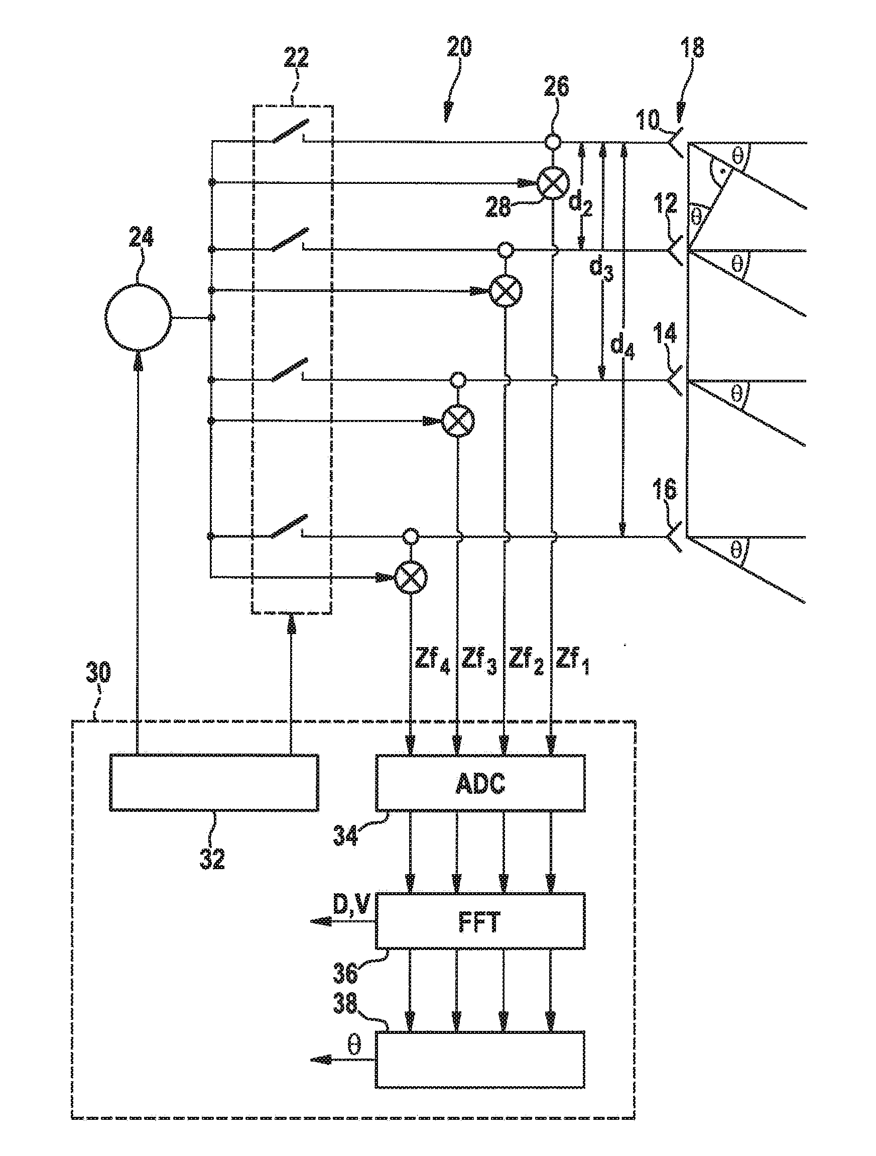
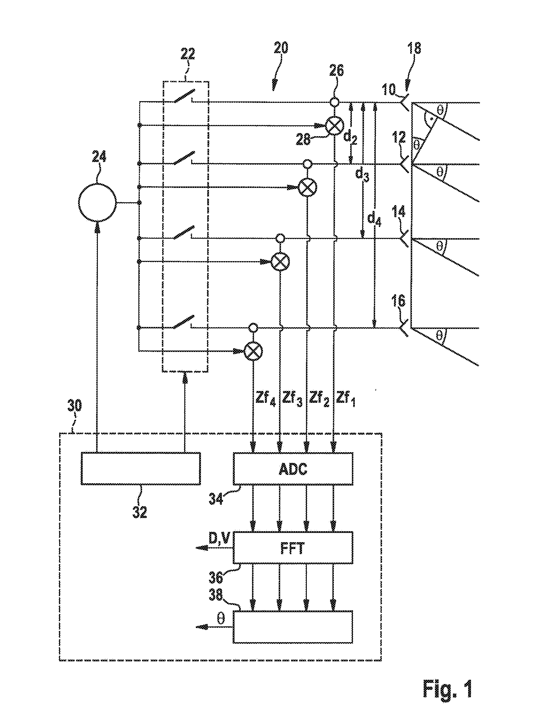
[0039]The radar sensor shown in FIG. 1 includes four antenna elements 10, 12, 14, 16, which together form a planar group antenna 18. The radar sensor is installed in a motor vehicle in such a way that antenna elements 10 through 16 are situated next to one another at the same level, so that an angular resolution capability of the radar sensor in the horizontal (in the azimuth) is achieved. FIG. 1 symbolically illustrates radar beams which are received by the antenna elements at an azimuth angle θ.

[0040]A high frequency portion 20 for controlling the antenna elements is formed, for example, by one or multiple monolithic microwave integrated circuits (MMICs), and includes a switching network 22 via which the individual antenna elements are selectively connectable to a local oscillator 24 which generates the radar signal to be transmitted. The radar echoes received by antenna elements 10 through 16 are each decoupled with the aid of a circulator 26 and supplied to a mixer 28, where the...


PUM


Abstract

An angle-resolving FMCW radar sensor, including multiple antenna elements in positions in a direction in which the radar sensor is angle-resolving and forming at least three transmitter arrays and at least one receiver array, and a control/evaluation device for an operating mode in which transmitter arrays periodically transmit signals whose frequency is modulated according to modulation ramps, and in which radar echoes of transmitted signals are received in by multiple antenna elements of the receiver array, and the located object angle is determined based on amplitude and/or phase relationships between radar echoes which correspond to different combinations of transmitter and receiver arrays. A measuring cycle of the radar sensor includes at least two periods in which in each case at least two combinations of transmitter and receiver arrays are alternated, and the combinations of transmitter and receiver arrays involved are different from one another for the at least two periods.

Description

FIELD OF THE INVENTION[0001]The present invention relates to an angle-resolving FMCW radar sensor, in particular for motor vehicles, including multiple antenna elements which are situated in various positions in a direction in which the radar sensor is angle-resolving and which form at least three transmitter arrays and at least one receiver array, and including a control and evaluation device which is configured for an operating mode in which the at least three transmitter arrays periodically transmit signals whose frequency is modulated according to a series of modulation ramps, and in which radar echoes of the transmitted signals are received in each case by multiple antenna elements of the at least one receiver array, and the angle of a located object is determined based on amplitude relationships and / or phase relationships between radar echoes which correspond to different combinations of transmitter arrays and receiver arrays.BACKGROUND INFORMATION[0002]Radar sensors are used ...

Claims


Application Information

Patent Timeline
Patent Type & Authority Applications(United States)
IPC IPC(8): G01S7/35H01Q3/24H01Q1/32G01S13/42G01S13/93G01S13/931
CPCG01S7/352G01S13/426H01Q3/247H01Q1/3233G01S13/931H01Q21/22H01Q3/2605H01Q25/00G01S13/003
Inventor SCHOOR, MICHAEL
Owner ROBERT BOSCH GMBH
Why Eureka
Try Eureka