Solid oxide fuel cell manufacturing method and dispenser apparatus for manufacturing same

a solid oxide fuel cell and manufacturing method technology, applied in the direction of cell components, final product manufacturing, sustainable manufacturing/processing, etc., can solve the problems of reducing the performance of constituted fuel cell elements, difficult to obtain a uniform thickness of applied slurry film, and insufficient control of the film thickness of each layer such as the fuel electrode layer, etc., to achieve high precision layer, efficient manufacturing, and dimensional precision

Inactive Publication Date: 2016-05-12
TOTO LTD
View PDF9 Cites 6 Cited by
  • Summary
  • Abstract
  • Description
  • Claims
  • Application Information

AI Technical Summary

Benefits of technology

[0076]In the method for manufacturing a solid oxide fuel cell of the present invention, an approximately uniform film thickness can be obtained, and manufacturing can be efficiently performed, even when the dimensional precision of the po...

Problems solved by technology

However, in the manufacturing method for a solid oxide fuel cell set forth in Japanese Published Unexamined Patent Application 2013-175305, the problem arises that the film thickness of each layer such as the fuel electrode layer, etc. cannot be adequately controlled.
However, if there is deflection of the cylindrical base tube, the spacing between the squeegee and the base tube will differ in each part of the base tube, making it difficult to obtain a uniform thickness of the applied slurry film.
When the film thickness of formed fuel electrod...

Method used


Image

  • Solid oxide fuel cell manufacturing method and dispenser apparatus for manufacturing same
  • Solid oxide fuel cell manufacturing method and dispenser apparatus for manufacturing same
  • Solid oxide fuel cell manufacturing method and dispenser apparatus for manufacturing same

Examples


first embodiment

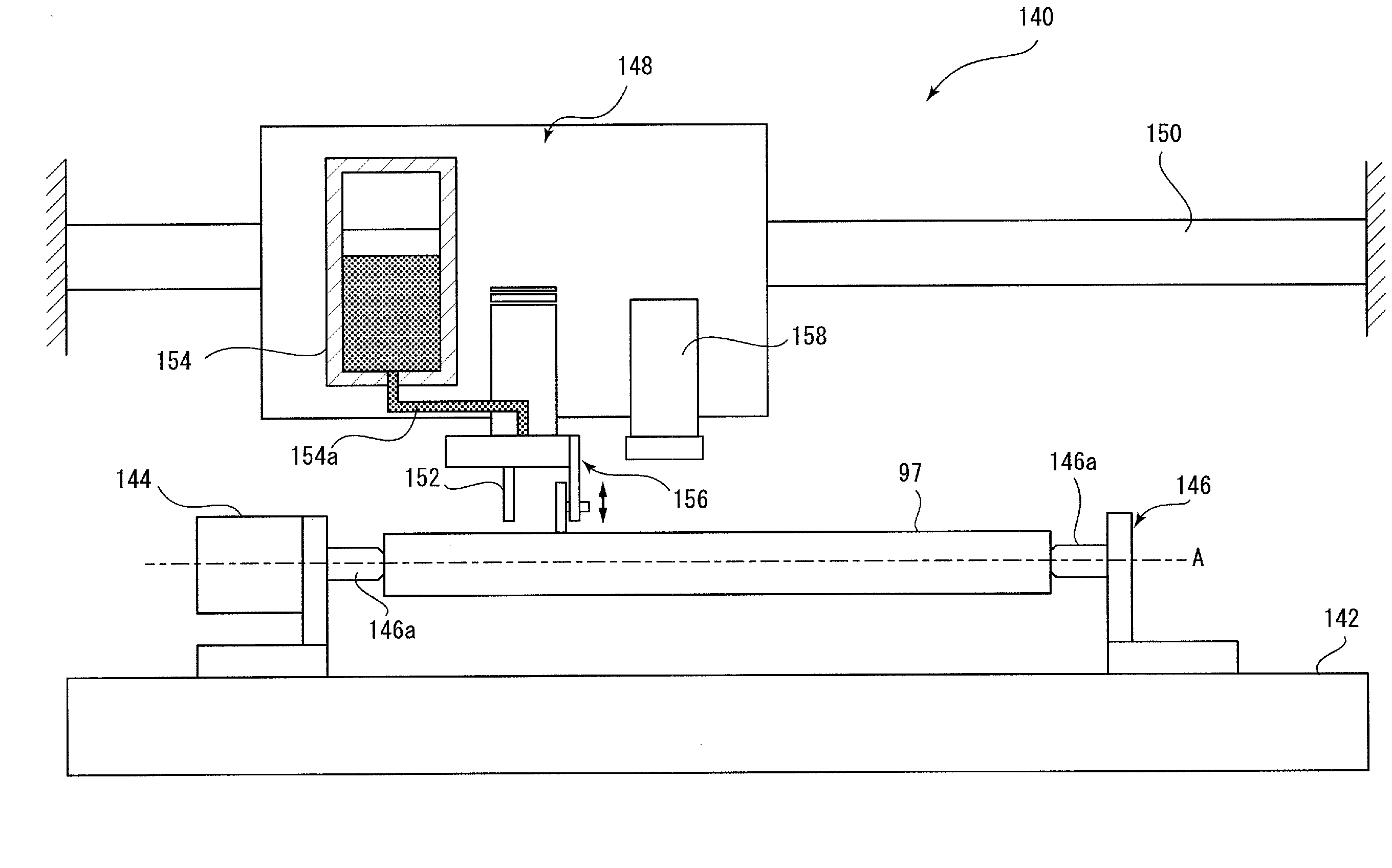
[0096]First, referring to FIGS. 1 through 16, we explain an individual solid oxide fuel cell according to the invention.

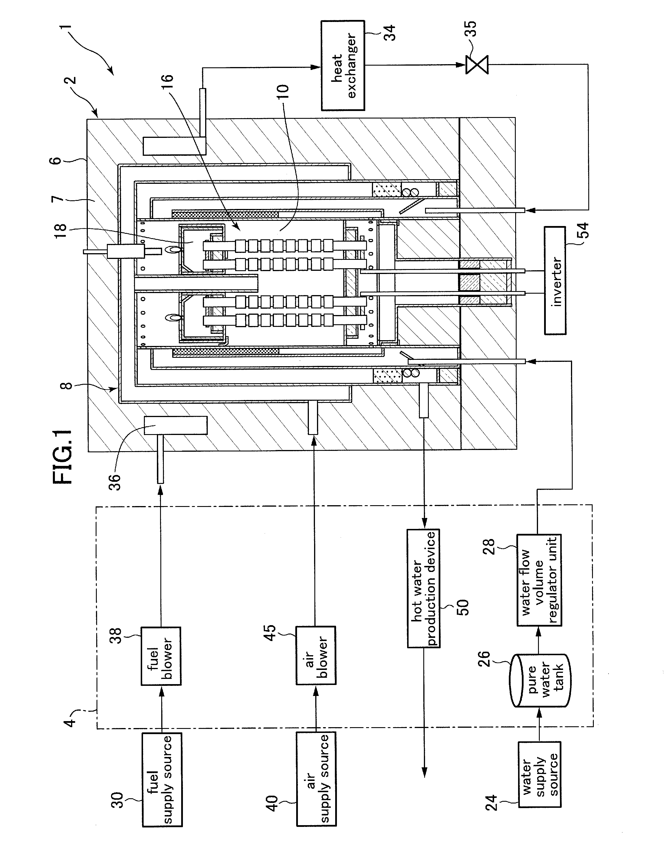
[0097]FIG. 1 is an overview configuration diagram showing a solid oxide fuel cell system containing individual solid oxide fuel cells according to a first embodiment of the invention. As shown by FIG. 1, the solid oxide fuel cell system 1 comprises a fuel cell module 2 and an auxiliary unit 4.

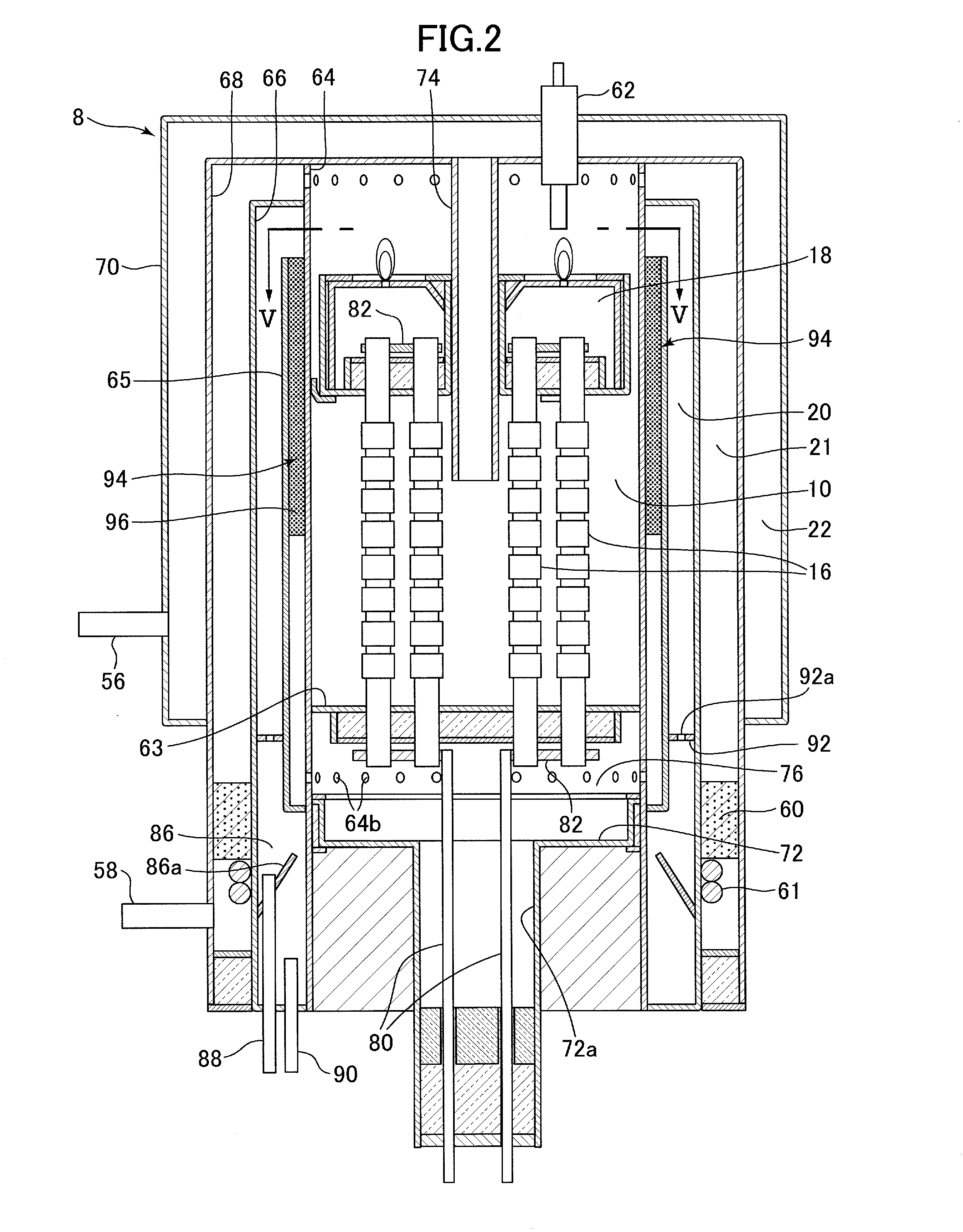
[0098]The fuel cell module 2 is furnished with a housing 6, and a fuel cell holding vessel 8 is formed within this housing 6, mediated by the heat storage material 7. A generating chamber 10 is provided inside this fuel cell holding vessel 8; multiple individual fuel cells 16 (individual solid oxide cells) are concentrically disposed within this generating chamber 10, and an electricity generating reaction between fuel gas and air serving as oxidant gas is performed by these individual fuel cells 16.

[0099]An exhaust collection chamber 18 is attached to the top end portion of e...

second embodiment

[0261]Next, referring to FIG. 17, we explain an individual solid oxide fuel cell according to the invention.

[0262]An individual fuel cell according to a second embodiment of the invention differs from the above-described first embodiment in that each of the three functional layers, being the fuel electrode layer, the electrolyte layer, and the air electrode layer, is respectively formed of two layers. Therefore here we explain only the aspects of the second embodiment of the invention different from the first embodiment of the invention, and we omit an explanation of similar constitutions, operations, and effects.

[0263]FIG. 17 is a cross-section showing an expanded view of a functional layer formed on the surface of a porous support body in an individual fuel cell according to a second embodiment of the invention.

[0264]As shown in FIG. 17, the individual fuel cells 200 of the present embodiment have a cylindrical porous support body 202 and three functional layers formed thereon, be...


PUM


Abstract

To provide a method of manufacturing a solid oxide fuel cell, capable of obtaining a uniform film thickness. The present invention is a method of manufacturing fuel cells (16), including a support body-forming step (S1) for forming a porous support body (97), a film deposition step for laminating functional layers constituting electricity generating elements on a support body; and a sintering step (S14, S16) for sintering the support body on which functional layers are formed; whereby the film deposition step includes surface deposition steps (S5, S11), in which a masking layer is formed in parts not requiring film deposition, and electricity generating elements first functional layers are simultaneously formed, and a dot deposition step (S15), in which slurry dots are formed by placing a slurry into a liquid droplet state and jetting it, and a second functional layer is formed by the agglomeration of these dots.

Description

RELATED APPLICATIONS[0001]This application claims priority under 35 U.S.C. §119 to Japanese Patent Application Nos. 2014-229701 filed on Nov. 12, 2014, 2014-229702 filed on Nov. 12, 2014, 2014-229705 filed on Nov. 12, 2014, 2015-098455 filed on May 13, 2015 and 2015-098456 filed on May 13, 2015, the entire contents of which are hereby incorporated by reference.BACKGROUND OF THE INVENTION[0002]1. Technical Field[0003]The present invention pertains to a method for manufacturing solid oxide fuel cells, and more particularly to a method for manufacturing a solid oxide fuel cell in which multiple electricity generating elements are formed on a porous support body and connected by an interconnector, and to a dispenser apparatus for said manufacturing.[0004]2. Background Art[0005]Solid oxide fuel cells (also referred to as “SOFCs” below) are fuel cells which operate at a relatively high temperature in which, using an oxide ion-conducting solid electrolyte as electrolyte, with electrodes at...

Claims


Application Information

Patent Timeline
IPC IPC(8): H01M8/12B05C11/00B05C5/02
CPCH01M8/1286B05C5/02H01M2300/0071H01M8/1246H01M2008/1293B05C11/00H01M8/10H01M8/1097H01M4/8828H01M8/004H01M8/243H01M4/8885H01M4/9033H01M8/0215H01M2250/405H01M2300/0074H01M8/2428Y02B90/10Y02E60/50Y02P70/50
Inventor FURUYA, SEIKIANDO, SHIGERUMOMIYAMA, YUTAKAHAYAMA, KIYOSHIOKAMOTO, OSAMUWATANABE, NAOKIISAKA, NOBUOSATO, MASAKIKAKINUMA, YASUOTANAKA, SHUHEIMURAKAMI, HIRONOBUHOSHIKO, TAKUYAKUBOTA, MASARUSHINOHARA, SHINJI
Owner TOTO LTD
Why Eureka
Try Eureka