

Skew adjustment circuit and skew adjustment method
- Summary
- Abstract
- Description
- Claims
- Application Information
AI Technical Summary
Benefits of technology
Problems solved by technology
Method used
Image

Examples
Embodiment Construction
[0053]Embodiments of the present invention will be described with reference to the drawings.
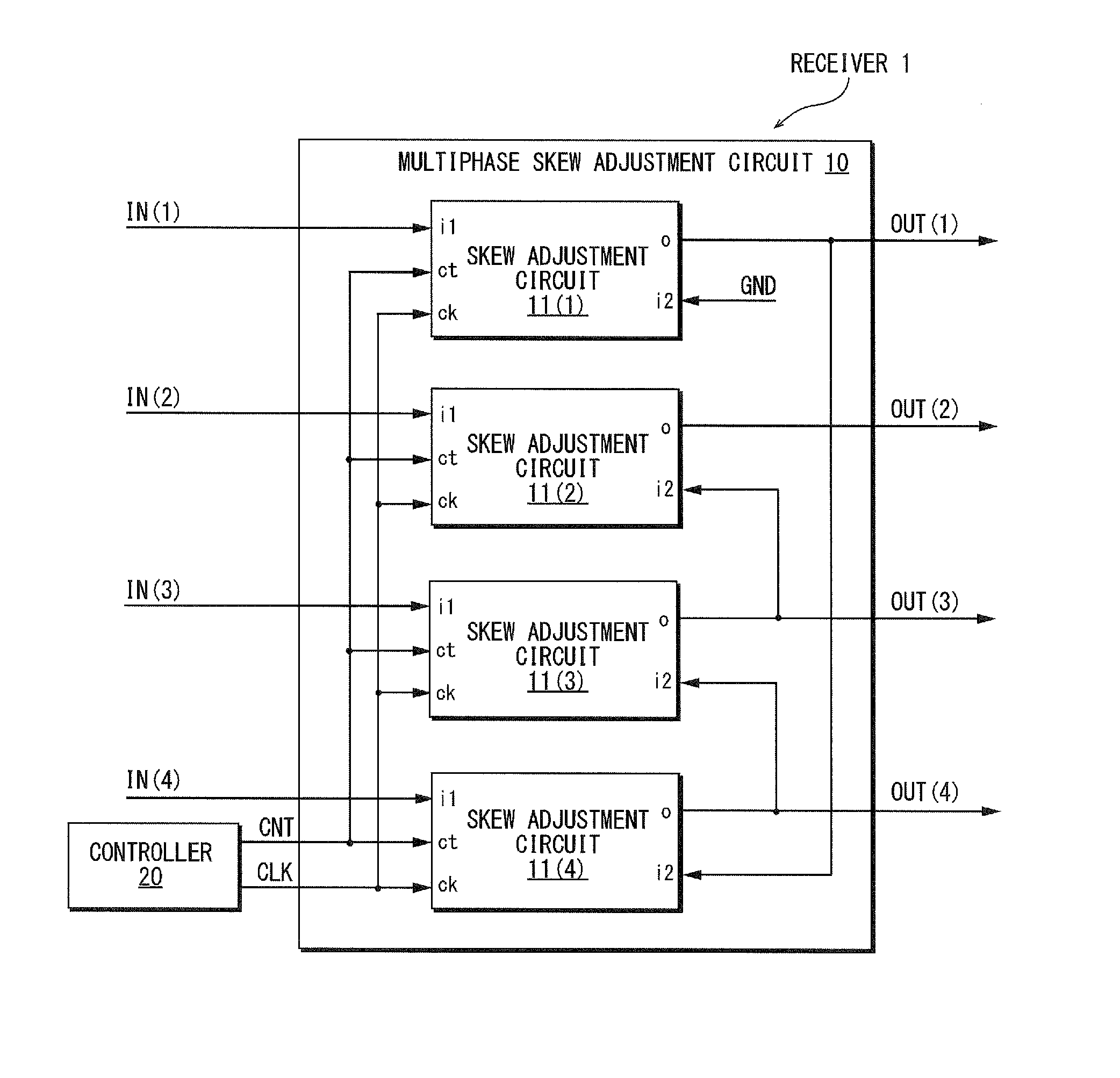
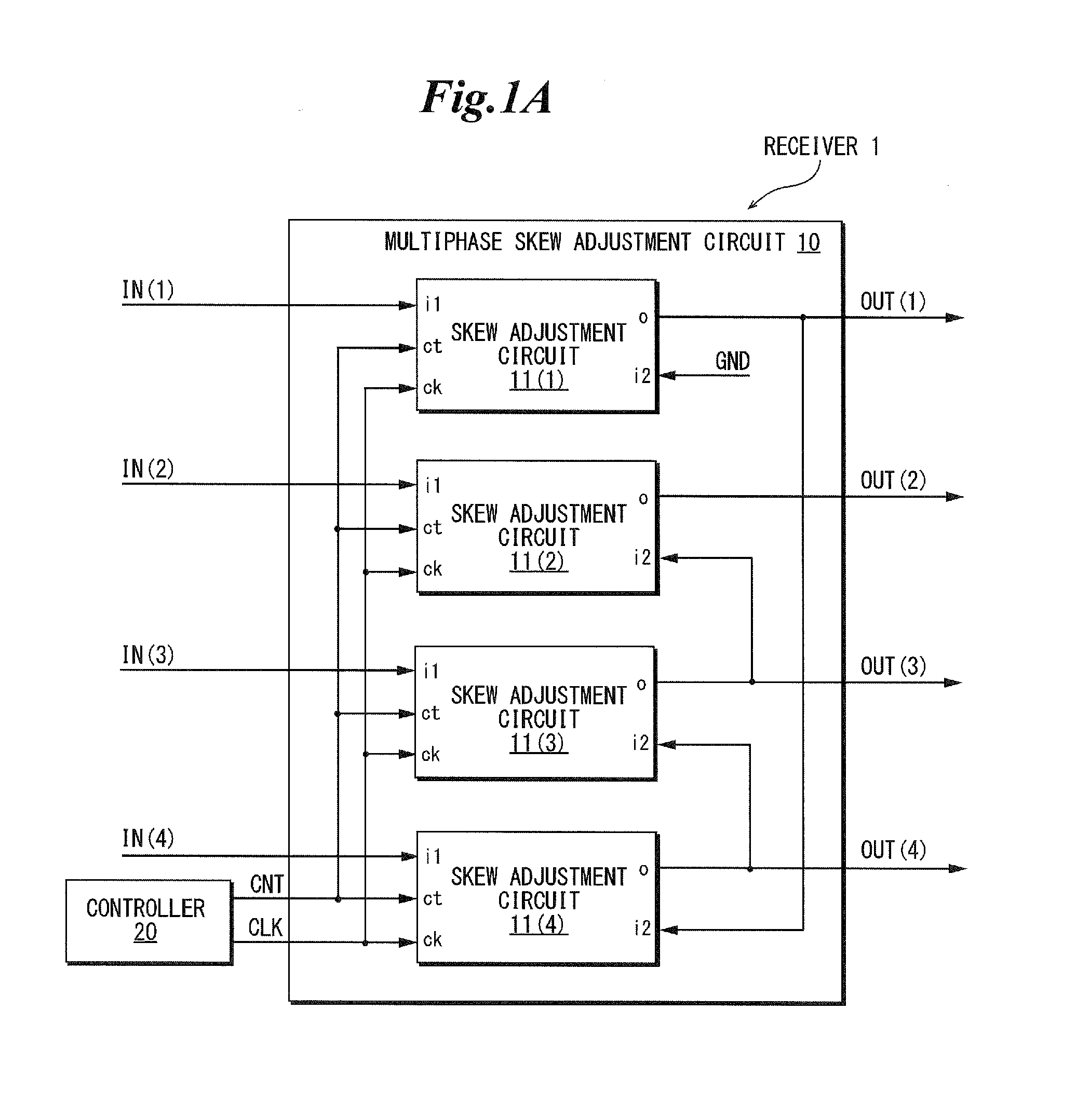
[0054]FIG. 1A is a diagram showing an example of a schematic configuration of a receiver according to an embodiment of the present invention. As shown in FIG. 1A, a receiver 1 of this embodiment may be configured to include, for example, a multiphase skew adjustment circuit 10 and a controller 20.
[0055]The multiphase skew adjustment circuit 10 may receive multiphase input clocks IN, adjust, based on a reference clock CLK, a skew generated between the multiphase input clocks IN, in accordance with a control signal CNT output from the controller 20, and output a result of the adjustment to the outside as multiphase output clocks OUT. For example, the multiphase skew adjustment circuit 10 may be configured to include a plurality of skew adjustment circuits 11(x) (x is a number for identifying the skew adjustment circuits 11). In this example, four skew adjustment circuits 11(1) to 11(4) are show...
PUM
 Abstract
Description
Claims
Application Information