
Standing Wave Electron Linear Accelerator and Container/Vehicle Inspection System

a technology of electron linear accelerator and container, which is applied in the direction of material analysis, material analysis using wave/particle radiation, instruments, etc., can solve the problems of low inspection efficiency, low inspection efficiency, and low inspection efficiency, and achieve the effect of low inspection efficiency

Active Publication Date: 2016-05-12
NUCTECH CO LTD
View PDF3 Cites 7 Cited by
  • Summary
  • Abstract
  • Description
  • Claims
  • Application Information

AI Technical Summary

Benefits of technology

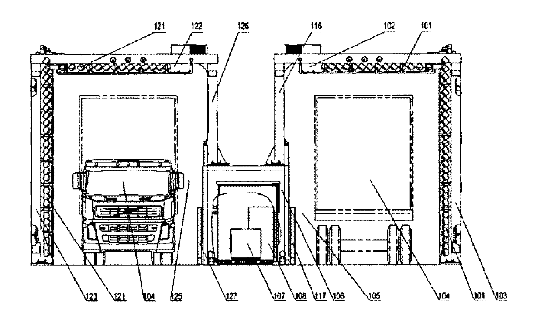
The present invention is a multi-target type standing wave electron linear accelerator that can simultaneously shoot multiple targets and form multiple X-ray beams. This invention also provides a container / vehicle inspection system that can conduct inspection based on dual-channel scanning, improving inspection efficiency.

Problems solved by technology

In regard to the container / vehicle inspection system, according to the prior art, the inspection system is a single-channel inspection system and the radiation source is a single target standing wave electron linear accelerator, so the inspection system can only transmit a continuous spectrum of X-rays to one scanning channel and is unable to conduct radiation imaging inspection for two containers / vehicles at the same time, thereby resulting in low inspection efficiency.
The mobile container inspection system of patent document 1 is also a one-channel inspection system and cannot conduct radiation imaging inspection for two containers at the same time, thereby resulting in low inspection efficiency.
According to the prior art described above, the inspection system is, however, also a single-channel inspection system and is unable to conduct radiation imaging inspection for two containers at the same time, thereby resulting in low inspection efficiency.

Method used


Image

  • Standing Wave Electron Linear Accelerator and Container/Vehicle Inspection System
  • Standing Wave Electron Linear Accelerator and Container/Vehicle Inspection System
  • Standing Wave Electron Linear Accelerator and Container/Vehicle Inspection System

Examples


example 1

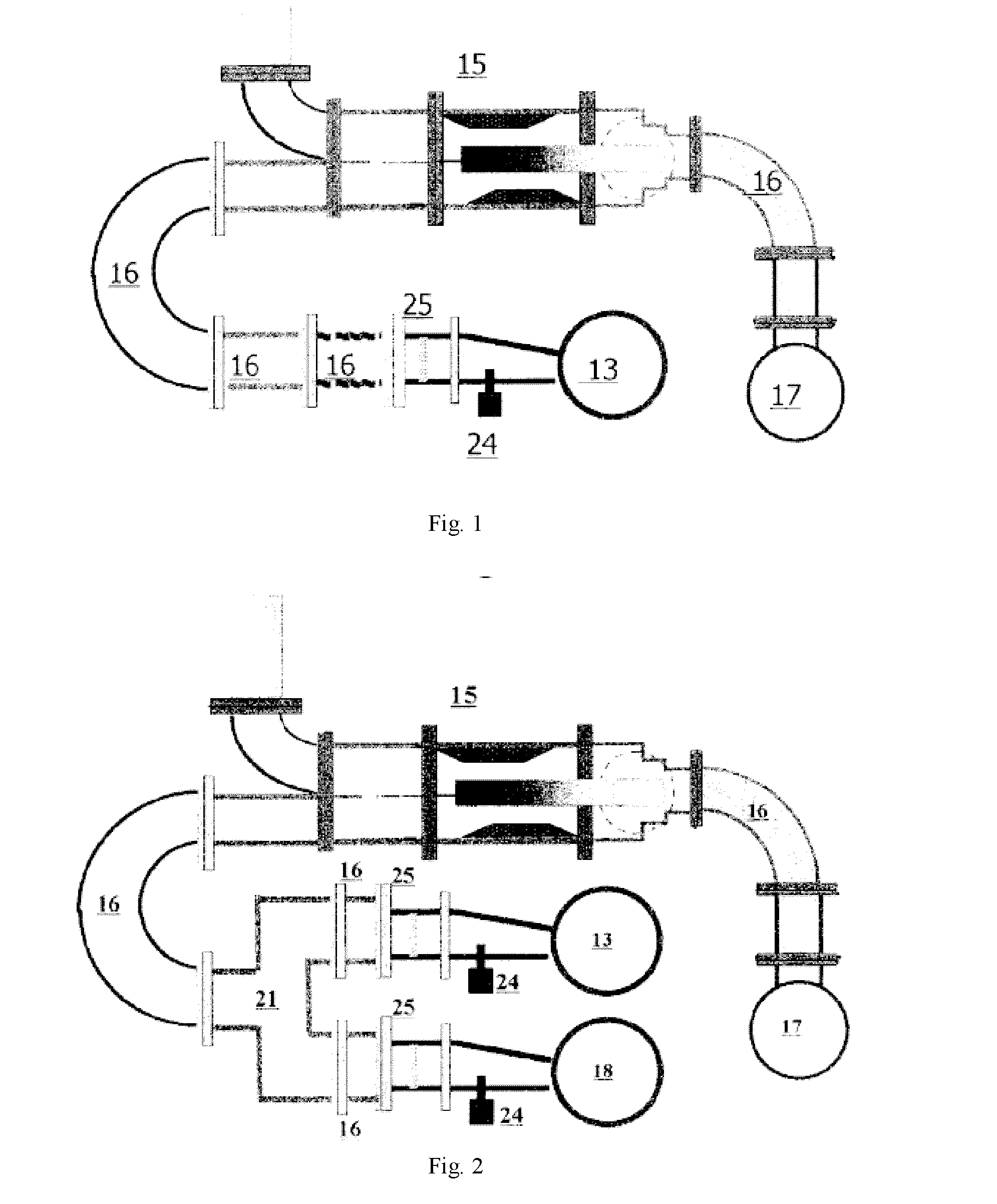
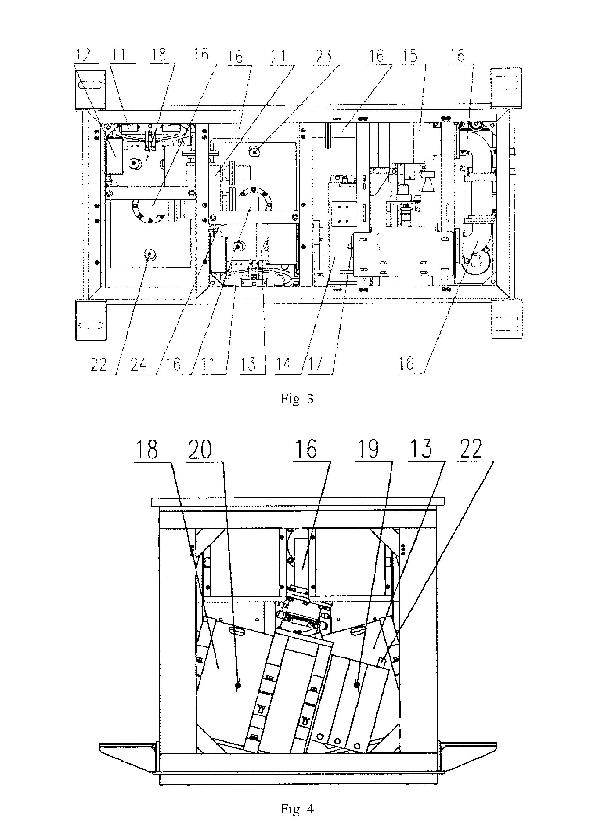
[0166]FIG. 2 is a schematic view of a standing wave electron linear accelerator (107, 207, 307) according to the present invention, FIG. 3 is a top view of an example of the standing wave electron linear accelerator according to the present invention, and FIG. 4 is a front view of an example of the standing wave electron linear accelerator according to the present invention. The left-right direction of FIG. 4 and the up-down direction of FIG. 3 are the left-right direction of the standing wave electron linear accelerator. When the standing wave electron linear accelerator is mounted onto a container / vehicle inspection system, the left-right direction of the container / vehicle inspection system shall be consistent with the left-right direction of the standing wave electron linear accelerator. The left-right direction of FIG. 3 and the direction perpendicular to the paper of FIG. 4 are the front-back direction of the standing wave electron linear accelerator. When the standing wave ele...

example 2

[0182]FIG. 5 is a top view of a further example of the standing wave electron linear accelerator according to the present invention, and FIG. 6 is a front view of the a further example of the standing wave electron linear accelerator according to the present invention, wherein the up-down direction of FIG. 5 and the left-right direction of FIG. 6 are the left-right direction of the standing wave electron linear accelerator. The content identical with or similar to the Example 1 is omitted and only differences will be explained.

[0183]In the present example, two accelerating tubes 13 and 18 are bilaterally symmetric. That is to say, two accelerating tubes 13 and 18 are symmetrically arranged in the up-down direction of FIG. 5 and the left-right direction of FIG. 6.

[0184]In addition, in the examples shown in FIGS. 3 to 6, the sectors formed of the X-ray beams emitted from two accelerating tubes 13, 18 respectively are along the left-right direction of the standing wave electron linear ...


PUM


Abstract

The present invention provides a standing wave electron linear accelerator comprising a modulator and a magnetron for producing radio frequency microwaves; a plurality of accelerating tubes for accelerating electrons; a microwave transmission system for feeding the microwaves into the plurality of accelerating tubes; a plurality of electron guns for emitting electron beams into the plurality of accelerating tubes; a plurality of targets impinged by the electrons from a plurality of accelerating tubes to form continuous spectrums of X-rays; a plurality of shielding devices for shielding the continuous spectrums of X-rays generated by the targets; and a microwave distributor disposed adjacent to the end of the microwave transmission system, wherein the microwave distributor has a microwave inlet and a plurality of microwave outlets for distributing the microwaves in the microwave transmission system into the accelerating tubes.

Description

CROSS-REFERENCE TO RELATED APPLICATIONS[0001]This application claims priority to PCT Application No. PCT / CN2013 / 001415, filed Nov. 19, 2013, published as WO2014 / 201594A1, entitled “Standing Wave Electron Linear Accelerator and Container / Vehicle Inspection System” and Chinese Patent Application No. 201310249082.9, filed on Jun. 21, 2013, published as CN104244561A, and entitled “Standing Wave Electron Linear Accelerator and Container / Vehicle Inspection System”, which are hereby incorporated by reference in their entirety.FIELD OF THE INVENTION[0002]The present invention relates to a standing wave electron linear accelerator, and a container / vehicle inspection system using the standing wave electron linear accelerator, and more particularly to a dual-channel fast-scan container / vehicle inspection system, a mobile container / vehicle inspection system and a relocatable container / vehicle inspection system.BACKGROUND[0003]Traditionally, radiation imaging technique has been widely used in co...

Claims


Application Information

Patent Timeline
Patent Type & Authority Applications(United States)
IPC IPC(8): H05H7/02G01V5/00H05H9/04
CPCH05H7/02H05H2007/027G01V5/0016H05H9/048H05H9/04G01V5/22
Inventor SUN, SHANGMINQIN, ZHANFENGYAO, SHENGYU, WEIFENGSONG, LIWEIZONG, CHUNGUANGLIANG, JINNING
Owner NUCTECH CO LTD
Learn More