Torque steering angle sensor

a technology of torque steering angle and sensor, which is applied in the direction of steering linkages, instruments, transportation and packaging, etc., can solve the problems of increasing cost, suppress the cost and size of torque steering angle sensor 2, and reduce the size of torque steering angle sensor 2

Active Publication Date: 2016-05-19
HITACHI METALS LTD
View PDF27 Cites 13 Cited by
  • Summary
  • Abstract
  • Description
  • Claims
  • Application Information

AI Technical Summary

Benefits of technology

[0116](Functions and Advantageous Effects of the Embodiment)
[0117]The above described embodiment has the following functions and advantageous effects.
[0118](1) The torsion of the torsion bar 113 causes the relative rotation between the ring magnet 31 and the first and second magnetic yokes 41 and 42, and the resulting variation in the magnetic field strength detected by the first magnetic field detecting element 61, depending on the angle of the relative rotation. This therefore makes the steering torque detectable. Also, since the magnetic field strengths the second magnetic field detecting element 62 receives from the ring magnet 31 and from the slide magnet 32, respectively, are detectable, the absolute value of the steering angle can mechanically be determined by the torque/steering angle computing portion 21. Furthermore, since the slide magnet 32 produces in the second magnetic field detecting element 62 a magnetic field in a different direction from that of the magnetic field of the ring magnet 31, the absolute value of the steering angle can be determined based on the detected result of one magnetic field det...

Problems solved by technology

On the other hand, although the torque sensor in the third embodiment of JP-A-2010-190632 is able to mechanically detect the absolute value of the steering angle, the two ...

Method used


Image

  • Torque steering angle sensor
  • Torque steering angle sensor
  • Torque steering angle sensor

Examples


first embodiment

[0057]Below is described a first embodiment of the present invention with reference to FIGS. 1 to 8B.

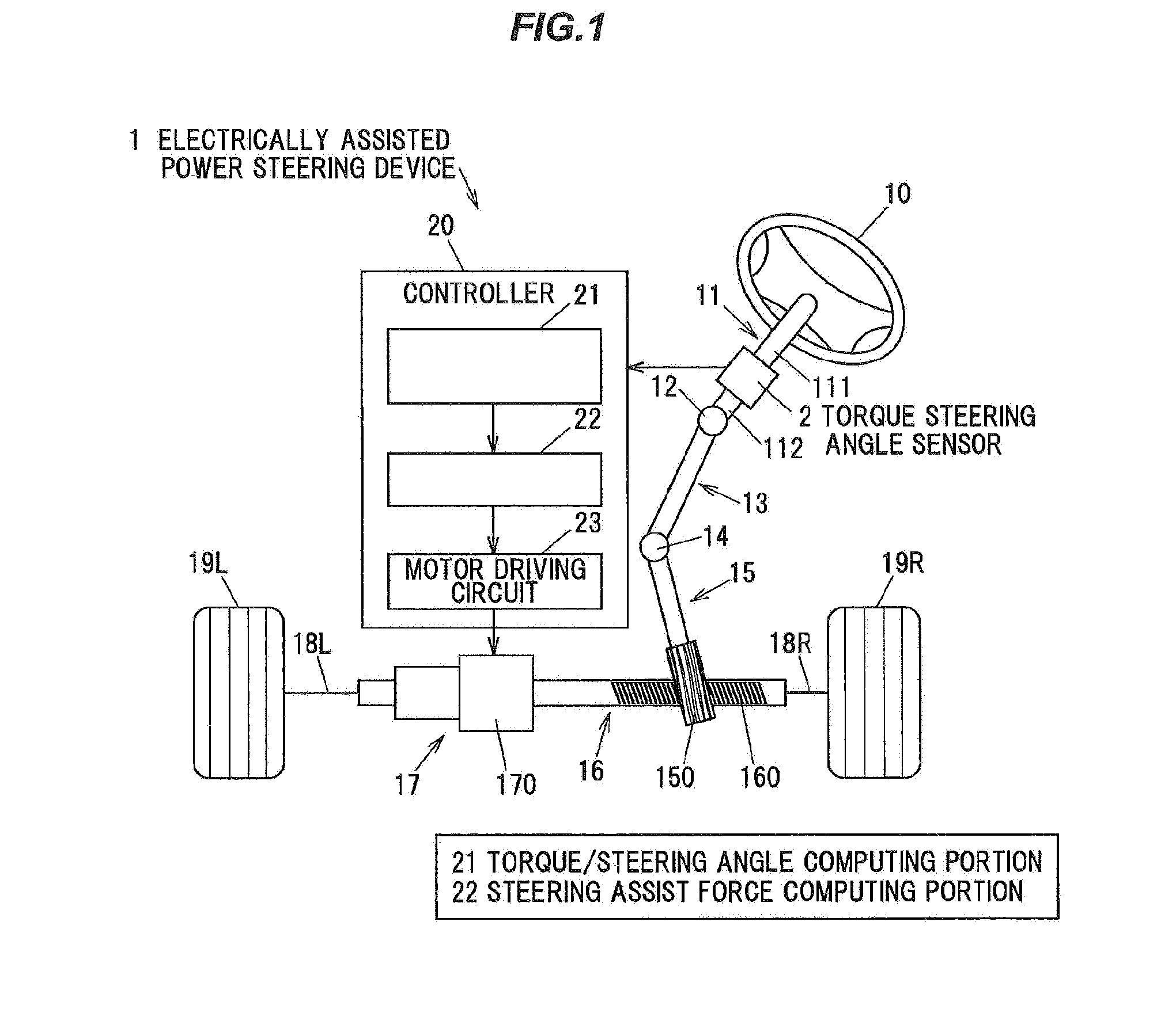
[0058]FIG. 1 is a schematic diagram showing an electrically assisted power steering device 1 to which a torque steering angle sensor in the first embodiment of the present invention is applied.

[0059]The electrically assisted power steering device 1 includes a steering shaft 11, which is connected to a steering wheel 10, an intermediate shaft 13, which is connected to the steering shaft 11 via a universal joint 12, a pinion shaft 15, which is connected to the intermediate shaft 13 via a universal joint 14, a rack shaft 16, which is provided with rack teeth 160 which mesh with pinion teeth 150 of the pinion shaft 15, a steering assist mechanism 17 to generate a steering assist force depending on a steering torque applied to the steering shaft 11 in steering of the steering wheel 10, and a torque steering angle sensor 2 to detect a steering angle and a steering torque of the steering wh...

second embodiment

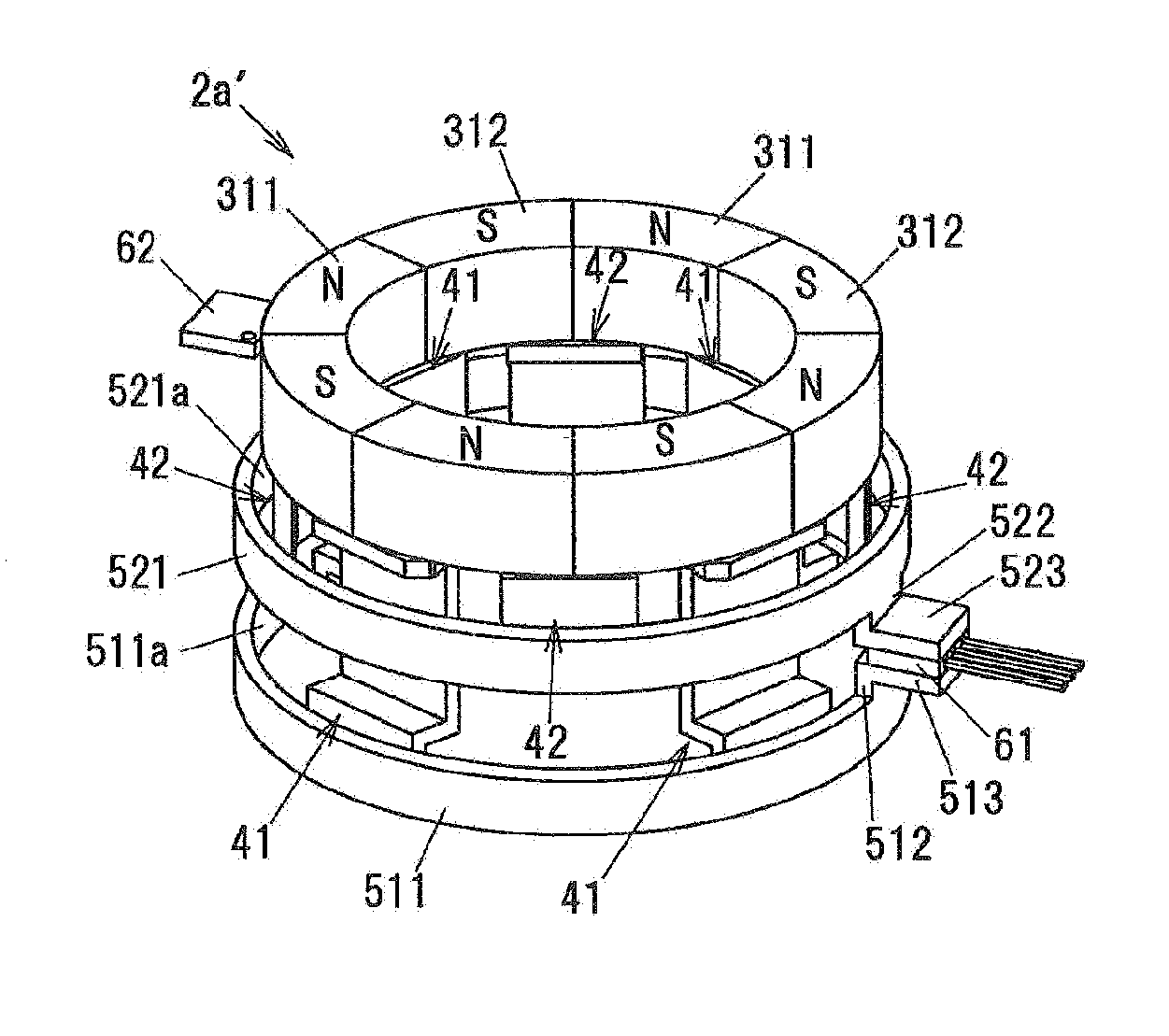
[0127]Next, a second embodiment of the present invention will be described with reference to FIGS. 9A to 9C. A torque steering angle sensor of the present embodiment is configured in the same manner as the torque steering angle sensor 2 in the first embodiment, except that a torque detecting portion 2a′ is configured in a different manner from the torque detecting portion 2a. Therefore, that torque detecting portion 2a′ different from the torque detecting portion 2a will be described in detail.

[0128]FIG. 9A is a perspective view showing a configuration of the torque detecting portion 2a′ of the torque steering angle sensor of the second embodiment, together with a second magnetic field detecting element 62. FIG. 9B is a perspective view showing a first magnetic yoke 41 constituting the torque detecting portion 2a′. FIG. 9C is a perspective view showing a second magnetic yoke 42 constituting the torque detecting portion 2a′.

[0129]Although in the first embodiment, it has been describ...


PUM


Abstract

A torque steering angle sensor is provided. The sensor includes a ring magnet with magnetic poles, magnetic path forming members to vary in location relative to the magnetic poles depending on torsion of a torsion bar, one pair of magnetic flux collecting rings for the magnetic path forming members, a first detecting element to detect a magnetic field between the flux collecting rings, a second detecting element to receive a magnetic field from the ring magnet, a slide magnet for producing a magnetic field in a different direction from that of the magnetic field of the ring magnet in the second detecting element, and a sliding mechanism to move the slide magnet toward or apart from the second detecting element with rotation of a rotary member of an electrically assisted power steering device. The second detecting element detects the magnetic fields received from the ring magnet and the slide magnet.

Description

[0001]The present application is based on Japanese patent application No. 2014-234226 filed on Nov. 19, 2014, the entire contents of which are incorporated herein by reference.BACKGROUND OF THE INVENTION[0002]1. Field of the Invention[0003]This invention relates to a torque steering angle sensor, which is capable of detecting a steering torque and a steering angle of a steering wheel of a vehicle.[0004]2. Description of the Related Art[0005]Conventionally, electrically assisted power steering devices for vehicles are provided with a torque sensor to be able to detect a steering torque. Such a torque sensor is able to detect a steering angle as well as the steering torque. See, e.g. JP-A-2010-190632.[0006]A torque sensor disclosed by JP-A-2010-190632 as a first embodiment includes a torsion bar for coupling together an input shaft and an output shaft of a steering shaft, a sensor yoke assembly, which is fixed to the input shaft of the steering shaft, a magnetic flux collecting yoke a...

Claims


Application Information

Patent Timeline
IPC IPC(8): G01L3/10B62D6/10
CPCB62D6/10G01L3/101B62D15/0215
Inventor IKEDA, YUKIO
Owner HITACHI METALS LTD
Why Eureka
Try Eureka