

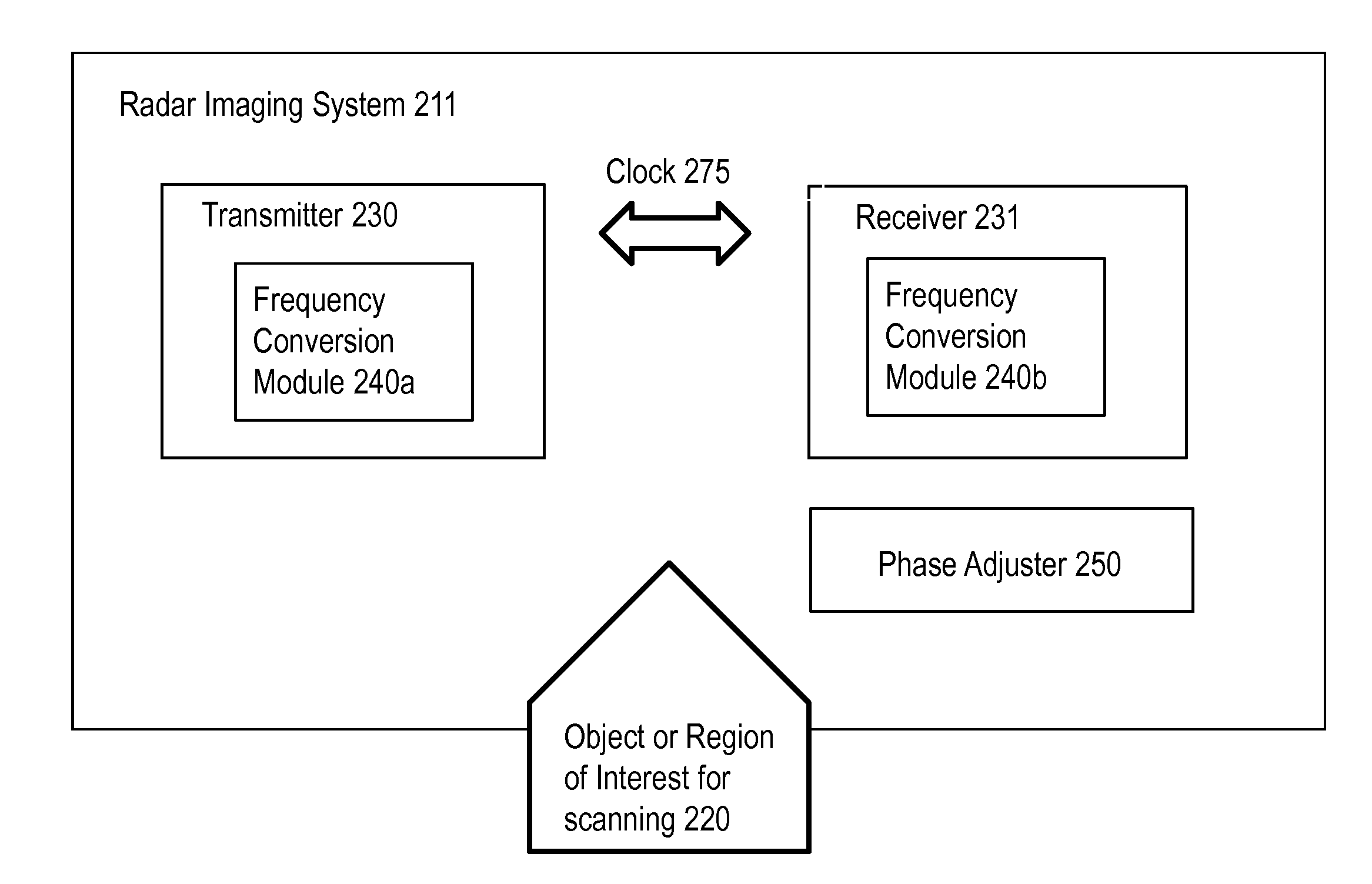
Modular superheterodyne stepped frequency radar system for imaging
a radar system and superheterodyne technology, applied in the field of radar-based imaging systems, can solve the problems of high hardware architecture cost, and high system performance of such systems, and achieve the effect of expanding the total operating system bandwidth, low cost, and synchronizing between transmitting and receiving modules relatively easy
- Summary
- Abstract
- Description
- Claims
- Application Information
AI Technical Summary
Benefits of technology
Problems solved by technology
Method used
Image

Examples
Embodiment Construction
[0025]For purposes of reading the description of the various embodiments below, the following descriptions of the sections of the specification and their respective contents may be helpful:[0026]Section A describes a network environment and computing environment which may be useful for practicing embodiments described herein; and[0027]Section B describes embodiments of systems and methods for establishing wideband radar for imaging.
A. Computing and Network Environment
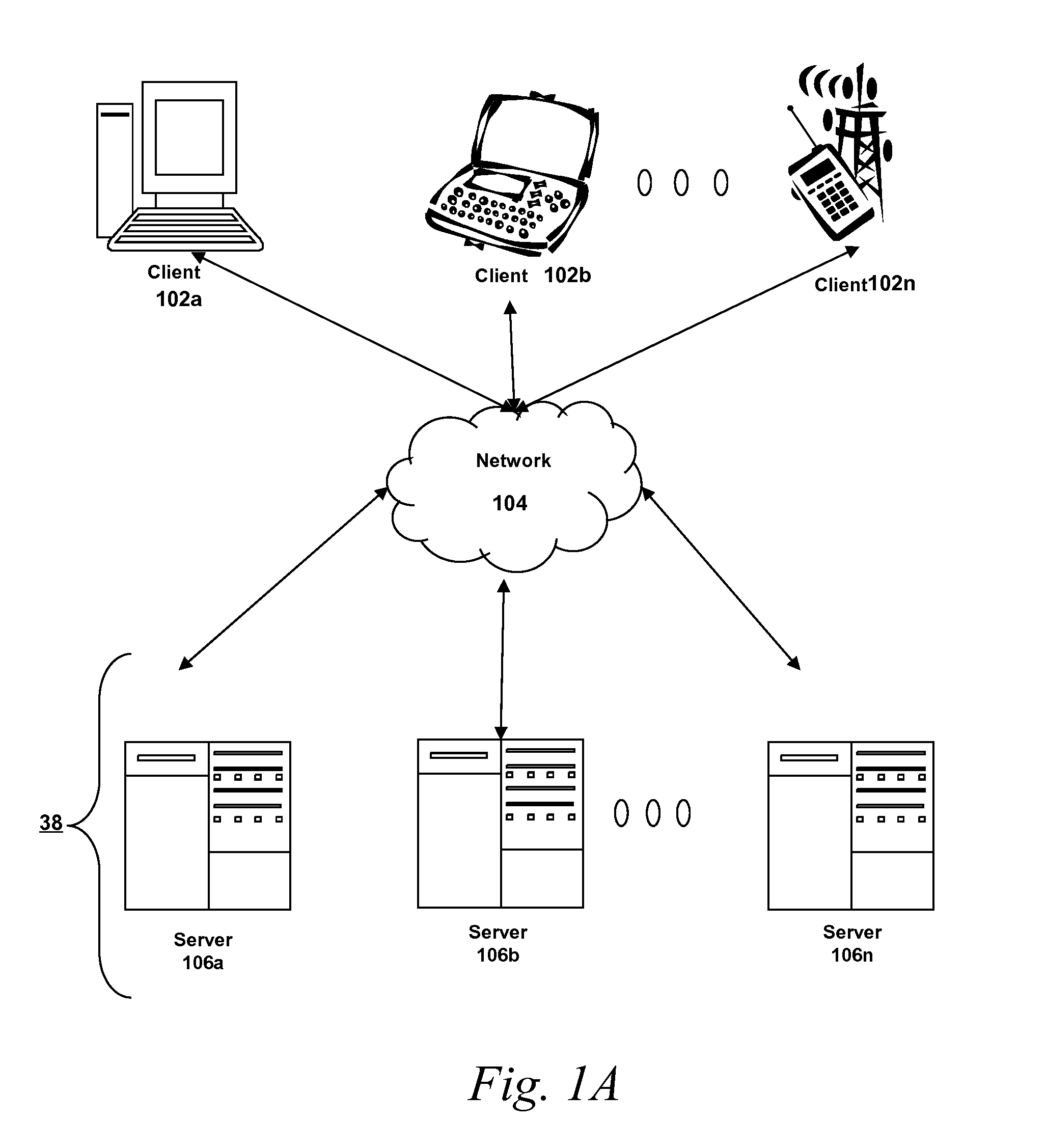
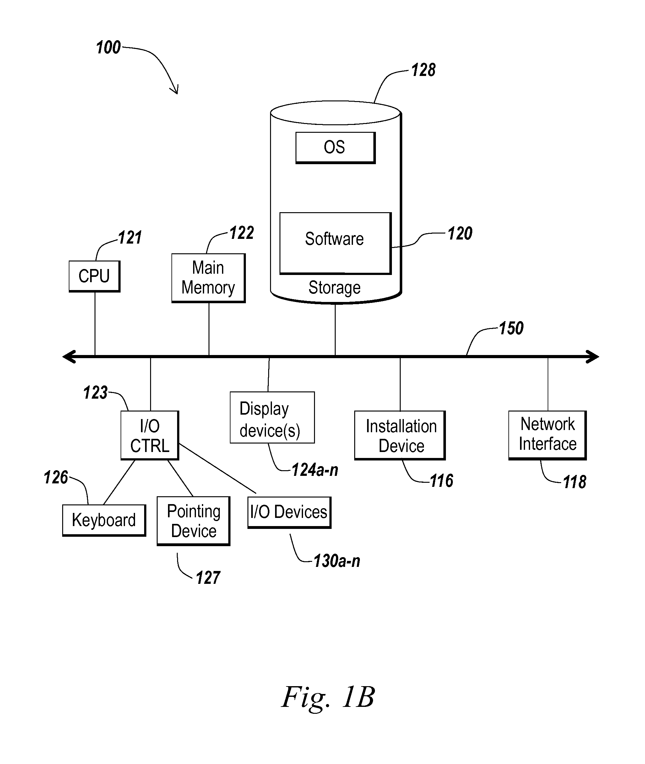
[0028]Prior to discussing specific embodiments of the present solution, it may be helpful to describe aspects of the operating environment as well as associated system components (e.g., hardware elements) in connection with the methods and systems described herein. Referring to FIG. 1A, an embodiment of a network environment is depicted. In brief overview, the network environment includes one or more clients 101a-101n (also generally referred to as local machine(s) 101, client(s) 101, client node(s) 101, client machine(...
PUM
 Abstract
Description
Claims
Application Information