Grinder

a technology of grinding mills and grinding plates, which is applied in the direction of solid separation, grain milling, gas current separation, etc., can solve the problems that the fan blades of the watts '601 grinding plates cannot be done on the fly, and achieve the effects of reducing material stress and metal fatigue, improving performance, and improving speed operation

Active Publication Date: 2016-05-26
SONTAG GLENNON C
View PDF6 Cites 19 Cited by
  • Summary
  • Abstract
  • Description
  • Claims
  • Application Information

AI Technical Summary

Benefits of technology

[0011]Other embodiments of the present invention make use of improved metallurgy. Previously the Watts '601 grinder, for example, was fabricated entirely of A36 carbon steel. Better performance is achieved by constructing the cutting hammers of AR400 steel alloy and constructing the cutting disks of A514 steel alloy. The cutting hammers formed of AR400 steel alloy withstand the harsh impact environment of the in-feed material and the cutting disks formed of A514 steel alloy do not defl

Problems solved by technology

This adjustment like adjusting the fan blades in

Method used


Image

  • Grinder
  • Grinder
  • Grinder

Examples


Embodiment Construction

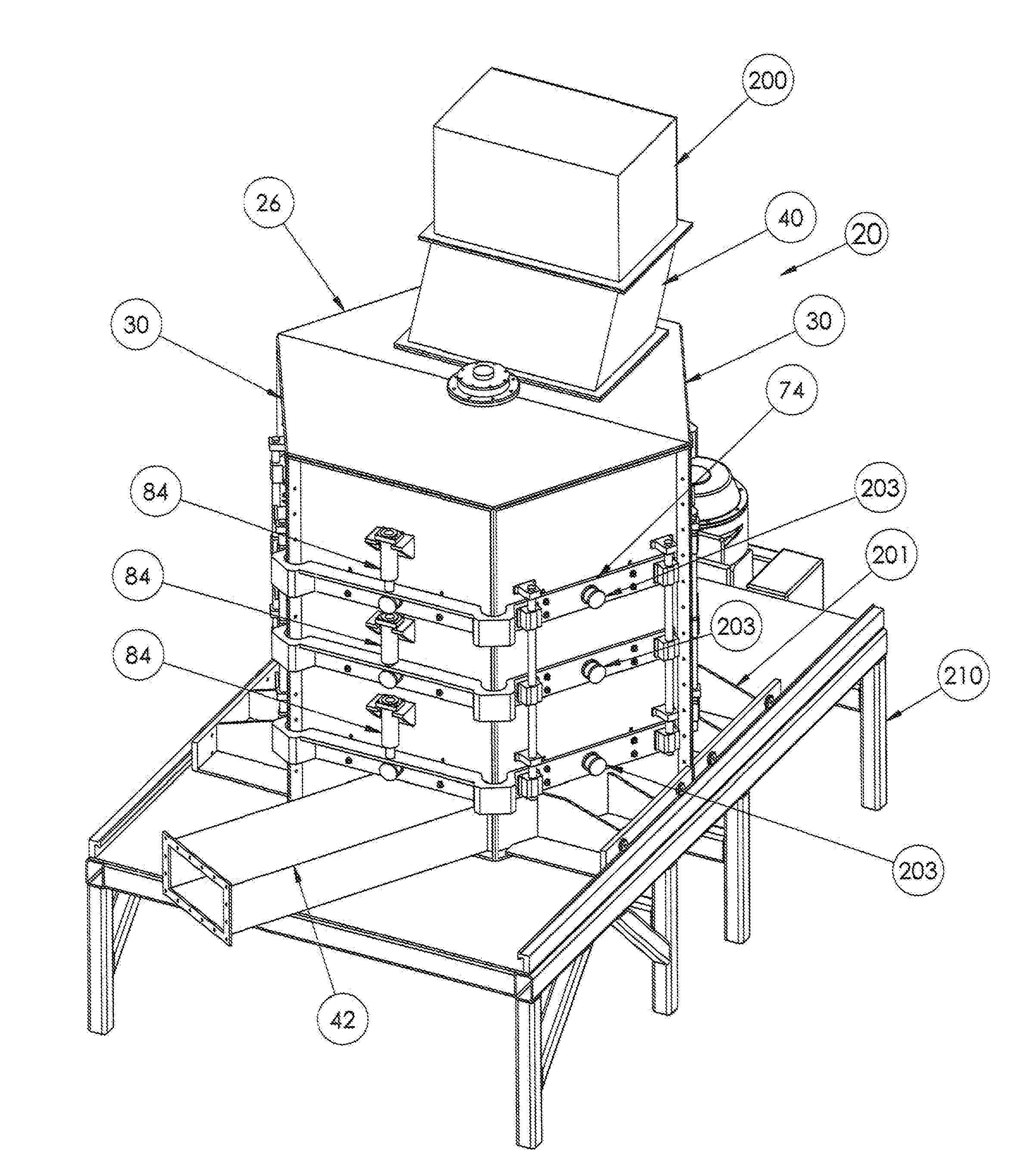
[0033]The following detailed description is merely exemplary in nature and is not intended to limit the described embodiments or the application and uses of the described embodiments. As used herein, the word “exemplary” or “illustrative” means “serving as an example, instance, or illustration.” Any implementation described herein as “exemplary” or “illustrative” is not necessarily to be construed as preferred or advantageous over other implementations. All of the implementations described below are exemplary implementations provided to enable persons skilled in the art to make or use the embodiments of the disclosure and are not intended to limit the scope of the disclosure, which is defined by the claims. For purposes of description herein, the terms “upper,”“lower,”“left,”“rear,”“right,”“front,”“vertical,”“horizontal,” and derivatives thereof shall relate to the invention as oriented in FIG. 1. Furthermore, there is no intention to be bound by any expressed or implied theory pres...


PUM


Abstract

A grinder having with a rotor and fan assembly mounted in a housing having one or more of the following features: Cutting shaft and fan shaft concentric and rotated by separate motors, housing formed in two sections with a line of division passing through the axis of rotation and mounted on rollers, ping pong shaped cutting hammers, deflectors attached to the inside of the housing and to a deflector assembly on the outside of the housing. The deflectors movable vertically and horizontally with first and second motion controllers for adjusting the spacing between the cutting hammers and the deflectors. A programmable logic controller for independently controlling the speed at which the cutting shaft and fan shaft are rotated and the spacing between the cutting hammers and the deflectors to produce a desired particle size reduction for a selected material.

Description

BACKGROUND OF THE INVENTION[0001]1. Field of the Invention[0002]The present invention relates to a grinder with a generally vertical, rotatable first shaft having at least one set of cutter discs driven thereby and a fan assembly mounted below the cutter blades on a second vertical, rotatable second shaft in position to receive output from the cutter blades. The first and second shafts are driven by separate motors. Other features will be apparent in view of the disclosure which follows.[0003]2. Brief Description of the Prior Art[0004]Grinders, shredders or mills are well known devices for reducing the particle size of a material. For example, U.S. Pat. No. 5,192,029 to Harris, U.S. Pat. No. 5,680,994 to Eide et al. and U.S. Pat. No. 7,950,601 to Watts disclose mills for grinding garbage. Each of these mills includes a rotor mounted in a octagonal housing. The rotor includes a generally vertical shaft and a plurality of blades mounted on the shaft. Garbage is admitted into the housi...

Claims


Application Information

Patent Timeline
IPC IPC(8): B02C13/288B02C13/282B02C13/14
CPCB02C13/14B02C13/288B02C13/282B02C13/16B02C23/18
Inventor SONTAG, GLENNON C.
Owner SONTAG GLENNON C
Why Eureka
Try Eureka