A Method of Producing an Explosive Emulsion Composition

a technology of composition and emulsion, which is applied in the direction of explosives, weaving, looms, etc., can solve the problems of reducing the energy-density of the resultant explosive material, and achieve the effect of increasing the total energy of the composition

Inactive Publication Date: 2016-05-26
ORICA INT PTE LTD
View PDF4 Cites 19 Cited by
  • Summary
  • Abstract
  • Description
  • Claims
  • Application Information

AI Technical Summary

Benefits of technology

[0016]In an embodiment of the invention, the manufacturing methodology employed in the MMDP and PM is suitably flexible so that the characteristics of the explosive composition (e.g. the distribution and / or the concentration of voids), and thus the blasting performance, can be varied with ease so that tailored blasting solutions can be provided between different blastholes in a blastfield.
[0018]As will be evident, preferably the MMDP / PM allows manufacture and loading into blastholes of explosive compositions without the use of augers and associated hydraulic drives or other heavy equipment. This enables process functionality, loading capacity and safety to be enhanced. The intention is to provide a seamless on-site manufacturing and blasthole loading system that is integrated in mobile form.
[0023]Importantly, this allows the energy release characteristics of an explosive composition to be understood and controlled by varying the combination of energetic liquids used and / or the arrangement of the energetic liquids within the bulk of the explosive composition. In turn this enables the detonation properties of the explosive composition to be tailored to particular rock / ground types and to particular mining applications. As will become clear, the formulations that may be produced in accordance with the present invention may be varied by components selection and / or by manipulating process parameters, such as flow rates of components, and / or by varying hardware componentry that is used. The invention may thus be readily applied to vary explosive formulation design, even between individual blastholes.

Problems solved by technology

Inclusion of an amount of voids (or cavities) over and above the critical amount required for sensitization will unnecessarily reduce the density of the composition and lead to reduced energy-density of the resultant explosive material.

Method used


Image

  • A Method of Producing an Explosive Emulsion Composition
  • A Method of Producing an Explosive Emulsion Composition
  • A Method of Producing an Explosive Emulsion Composition

Examples


specific embodiment 1

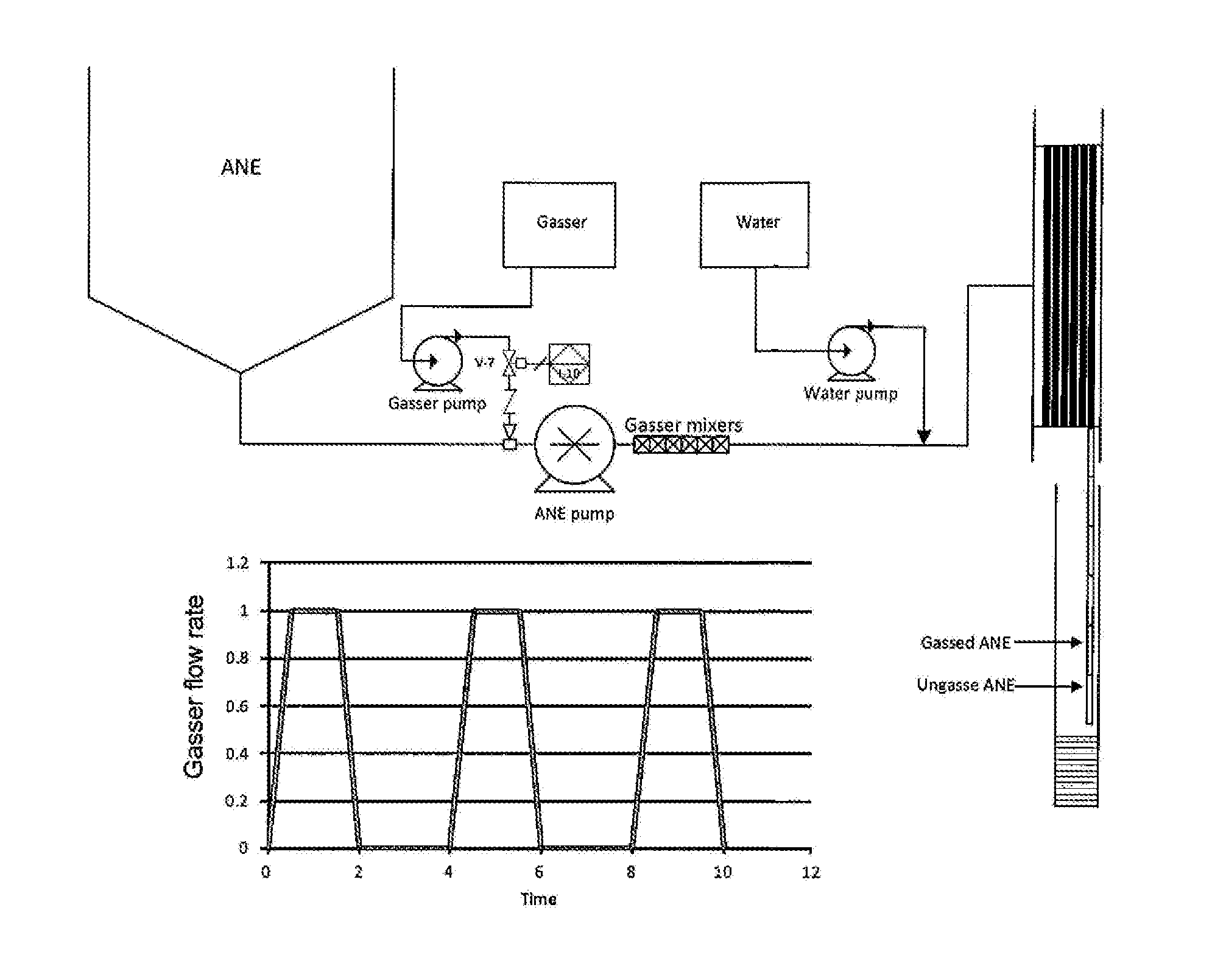
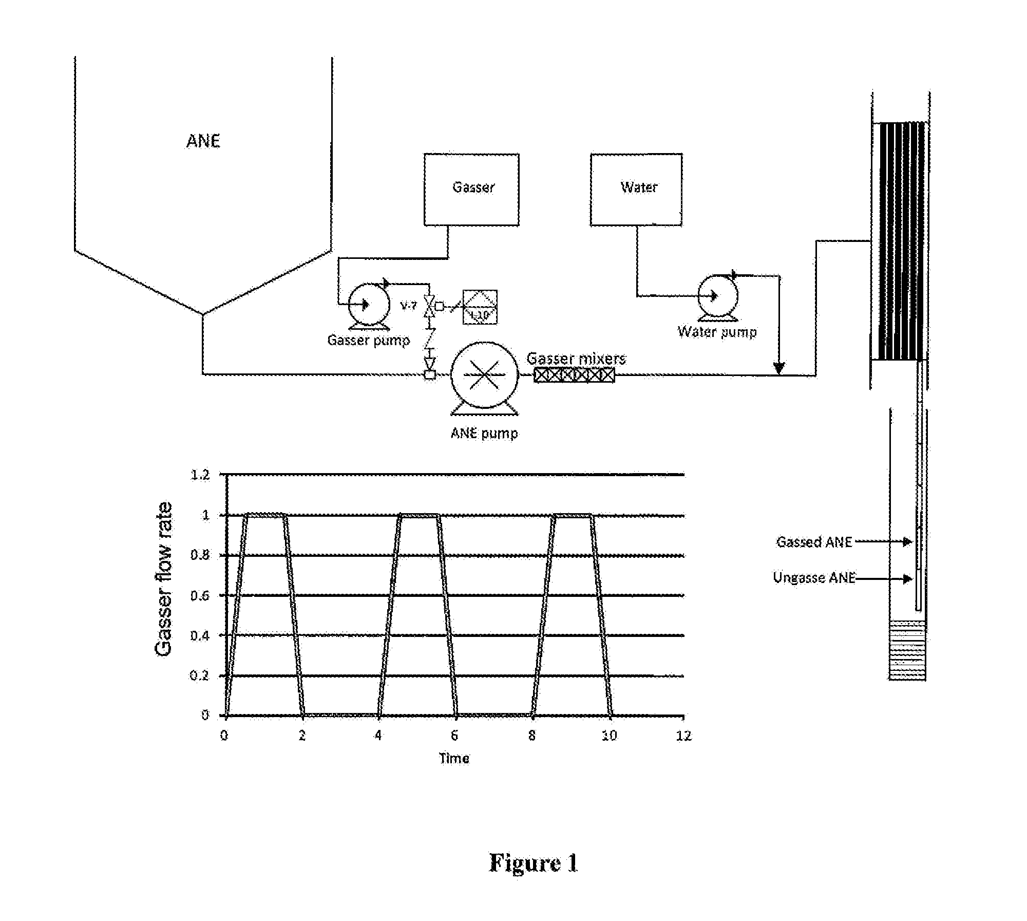
[0068]This specific embodiment is illustrated in FIG. 1.

[0069]FIG. 1 illustrates an apparatus that may be used to implement an embodiment of the present invention. In the embodiment shown, a chemical gassing solution is used to provide sensitizing voids in the liquid energetic material. The apparatus includes a storage vessel / tank for liquid energetic material (unsensitized ammonium nitrate emulsion; ANE), a single emulsion pump for delivering a flow of emulsion through a line, a chemical gasser solution delivery system, a static mixer (e.g. an SMX type mixer) for dispersing the chemical gasser solution (e.g. sodium nitrite solution), a water system for hose lubrication and a delivery hose.

[0070]The chemical gasser solution delivery system includes a flow control valve, which can be rapidly opened and closed thereby delivering carefully metered pulses of chemical gasser solution into the flowing liquid energetic material. Alternatively, a reciprocating pump, such as a piston or diap...

example 4

MOE 50 at 1.22 g / cm3

[0177]This example demonstrates the performance of MOE50, i.e. a mixture of emulsion with 50% mass gassed and 50% ungassed emulsion.

[0178]MOE50 was prepared using the apparatus mentioned in Example 2. The base emulsion (density 1.32 g / cm3) was delivered by two progressive cavity pumps, PC1 and PC2 and was identical to the previous two examples. PC1 pumped ungassed emulsion at a flow rate of 3 kg / min. PC2 delivered emulsion at 3 kg / min with gasser (4% NaNO2 solution) injected by a gasser (gear) pump. The void rich and void free emulsions were blended by a static mixer consisting of three helical mixing elements and loaded into cardboard tubes with internal diameters ranging from 70 to 180 mm. The gassed emulsion target density was 1.13 g / cm3 providing an overall density of 1.22 g / cm3 for the mixture of gassed and ungassed emulsion.

[0179]Charges were initiated with a single 400 g Pentex PPP booster with VOD measured with an MREL handitrap VOD recorder. The VOD ran...

example 1

Gassed emulsion at 1.22 g / cm3

[0266]This example demonstrates the performance of conventional gassed emulsion with random void distribution at a density of 1.22 g / cm3.

[0267]The starting emulsion at a density of 1.32 g / cm3 was delivered by a progressive cavity pump at a rate of 3 kg / min. A 4% / 0 mass sodium nitrite solution was injected into the flowing emulsion stream at a rate of 16 g / min by means of a gasser (gear) pump and dispersed in a series of static mixers. 1 m long cardboard tubes with internal diameters ranging from 40 to 180 mm were loaded with emulsion and allowed to gas. Charges were fired once the sample cup reached the target density of 1.22 g / cm3.

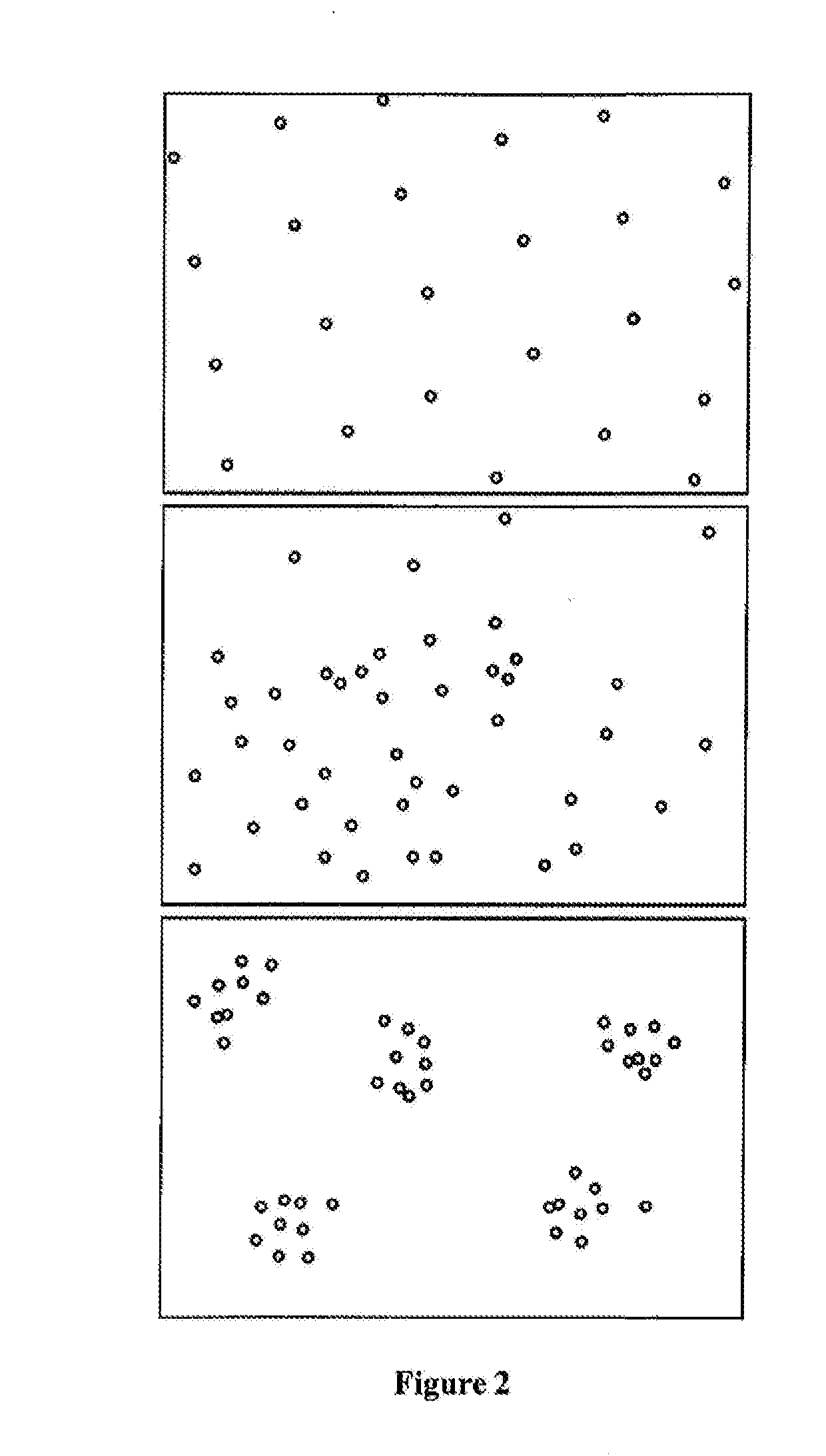
[0268]A sample of the emulsion was taken for DF analysis according to the procedure described above. FIG. 16 shows the void positions for conventional gassed emulsion. The cumulative distribution function is plotted in FIG. 17 and the differential plotted in FIG. 18. The cumulative distribution function shows a steep curve, w...


PUM

PropertyMeasurementUnit
volumeaaaaaaaaaa
internal diameteraaaaaaaaaa
diameteraaaaaaaaaa

Abstract

A method of producing an explosive composition comprising a liquid energetic material and sensitizing voids, the sensitizing voids being present in the liquid energetic material with a non-random distribution, which method comprises: providing a flow of liquid energetic material; and delivering sensitizing voids into the flow of liquid energetic material in a series of pulses to provide regions in the liquid energetic material in which sensitizing voids are sufficiently concentrated to render those regions detonable and regions in the liquid energetic material in which the sensitizing voids are not so concentrated.

Description

TECHNICAL FIELD[0001]The present invention relates to the manufacture of explosive compositions, in particular emulsion explosive compositions that are tailored to provide desired blasting properties. The present invention also relates to the integration of such manufacture in a blasting operation in which the explosive composition that is manufactured is provided in a blasthole.BACKGROUND[0002]Detonation energy of commercial explosives can be broadly divided into two forms—shock energy and heave energy. Shock energy fractures and fragments rock. Heave energy moves blasted rock after fracture and fragmentation. In general the higher the velocity of detonation (VOD) of an explosive the higher proportion of shock energy the explosive is likely to exhibit.[0003]Certain mining applications require the use of explosives that exhibit a combination of low shock energy and high heave energy. This allows fragmentation to be controlled (high shock energy produces significant amounts of dust s...

Claims


Application Information

Patent Timeline
Patent Type & Authority Applications(United States)
IPC IPC(8): C06B21/00F42D3/04F42D1/10
CPCC06B21/0008F42D3/04F42D1/10C06B23/003C06B23/004
Inventor ZANK, JOHANNRAYSON, MARK STUARTSUJANSKY, VLADIMIRWALTER, JAMESKIRBY, IAN JOHNCOOPER, JOHN
Owner ORICA INT PTE LTD
Why Eureka
Try Eureka