Fuel pumping unit

a technology of fuel pumping unit and pumping chamber, which is applied in the direction of machines/engines, liquid fuel engines, positive displacement liquid engines, etc., can solve the problems of difficult operation of both pumps efficiently, and achieve the effect of reducing any increase in fuel temperatur

Active Publication Date: 2016-05-26
ROLLS ROYCE PLC
View PDF5 Cites 17 Cited by
  • Summary
  • Abstract
  • Description
  • Claims
  • Application Information

AI Technical Summary

Benefits of technology

[0017]When the fuel pumping unit has the selector valve, it may further have a positive displacement start pump which is driven by the drive input via the gear arrangement, the selector valve being further configured to selectably provide a start mode, wherein: in the start mode the low pressure pump supplies fuel at the boosted pressure to the start pump for onward supply to the fuel metering unit, and the fuel supply from the low pressure pump to the high pressure pump is shut off such that the high pressure pump runs dry. Such an arrangement allows the pump unit to better supply sufficient pressure rise at low speed starts, e.g. at the low windmill relight speeds prevalent on modern high bypass turbofan engines. The start pump can also help to prime the centrifugal pumps should significant amounts of air have entered the centrifugal pumps. In the high and low pressure modes, rather than the selector valve having further complexity to isolate the start pump, the start pump can recirculate fuel between the start pump and the selector valve. This recirculation can be at a low pressure rise to reduce any fuel temperature increase in the start pump. The start pump is a positive displacement pump such as, an external gear, a gerator or a vane pump. In particular, it may be a vane pump such as a dual lobe vane pump. Conveniently, the low pressure pump and the start pump may be driven at the same speed by the drive input. For example, they may be mounted on a common shaft.

Problems solved by technology

The efficiencies of centrifugal pumps typically vary with rotational speed, and a problem with the arrangement of EP A 0657651 is that the two pumps operate at the same speed, making it difficult to operate both pumps efficiently.

Method used


Image

  • Fuel pumping unit
  • Fuel pumping unit
  • Fuel pumping unit

Examples


first embodiment

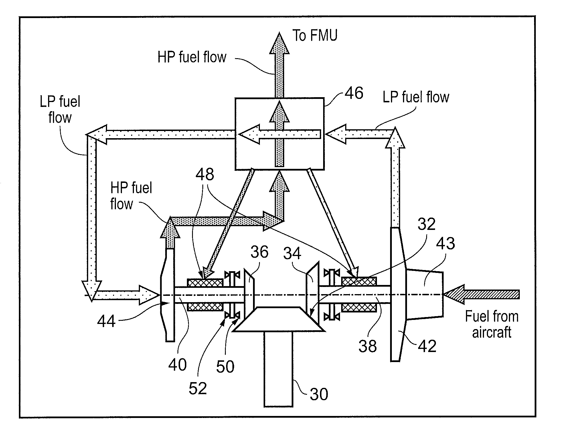
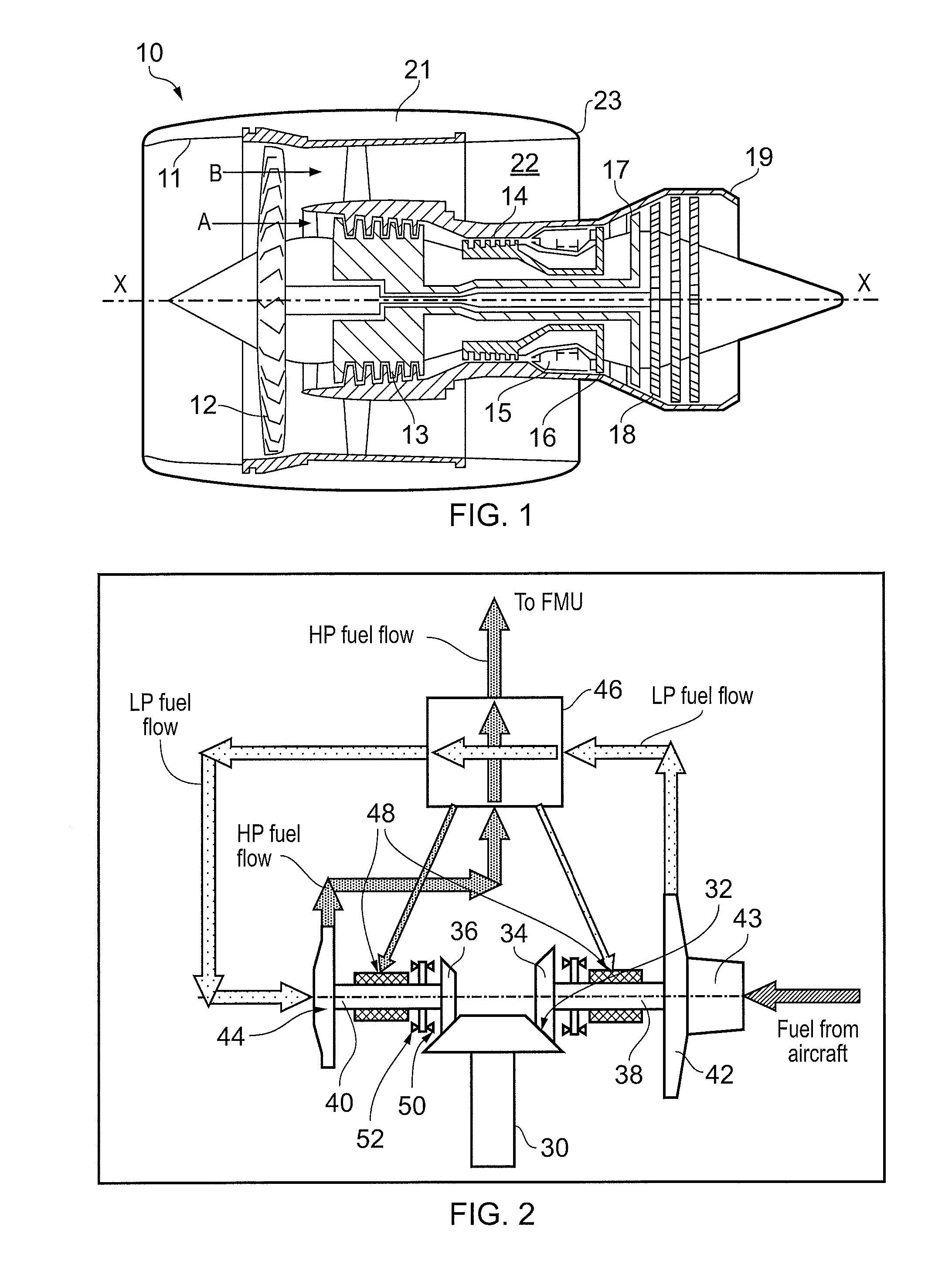
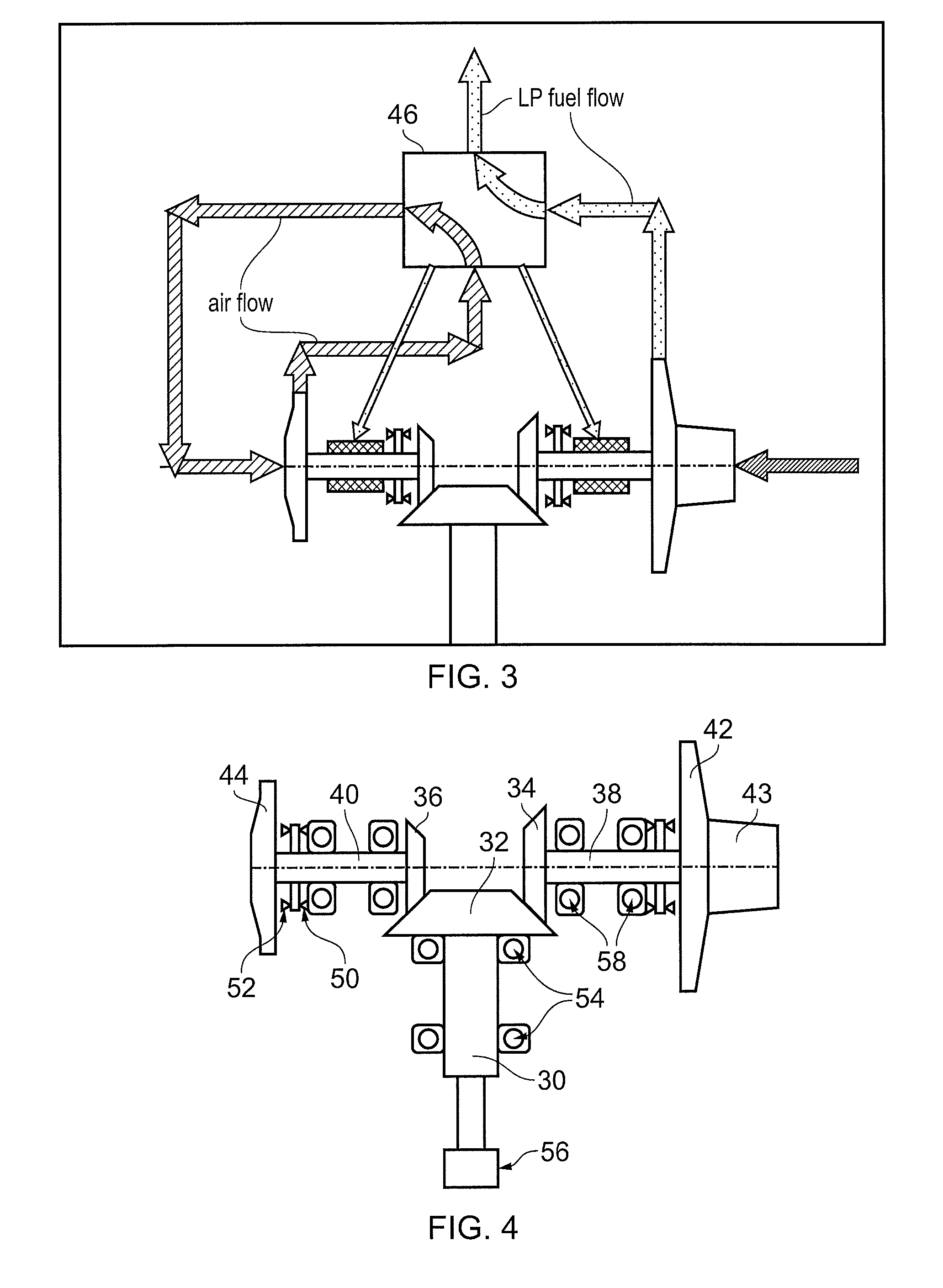
[0040]FIGS. 2 and 3 show schematically the fuel pumping unit having first stage (LP) and second stage (HP) centrifugal pumps, fuel flows being indicated by thick arrowed lines. A drive input 30 from the engine accessory gearbox terminates in a bevel gear 32. Further bevel gears 34, 36 at the ends of first stage 38 and second stage 40 impeller shafts mesh with the input bevel gear. At the other ends of the impeller shafts are mounted first stage 42 and second stage 44 impellers of respectively the first and second stage centrifugal pumps. The first stage can incorporate an axial flow inducer 43.

[0041]Together, the bevel gears 32, 34, 36 form a gear arrangement operatively located between the drive input 30 and the low and high pressure pumps. The first stage bevel gear 34 is larger diameter than the second stage bevel gear 36, making the first stage pump run at a slower speed than the second stage pump. More particularly, the first stage pump can be run at a low speed compatible with...

second embodiment

[0056]FIGS. 8 to 10 show schematically the fuel pumping unit.

[0057]The pumping unit of the second embodiment has additional features which address:[0058]Low speed start: Centrifugal pumps typically do not provide enough pressure rise for engine starting; especially at the low windmill relight speeds prevalent on modern high bypass turbofan engines.[0059]Priming: If significant amounts of air enter a centrifugal pump it may not generate a sufficient pressure rise since the rise is proportional to the density of the fluid being pump. As a consequence, it may not be possible for the pump to dispel the air from the system and re-prime itself.

[0060]Accordingly, in the second embodiment, the pumping unit has a positive displacement start pump 60 that can be mounted on the first stage impeller shaft 38 to provide engine starting / priming capability. The selector valve 46 has a third position, illustrated in FIG. 8, which provides a start mode in which the flow output from LP pump is routed ...


PUM


Abstract

A fuel pumping unit has a low pressure centrifugal pump and a high pressure centrifugal pump. In use, the low pressure pump supplies fuel at a boosted pressure to the high pressure pump for onward supply to a fuel metering unit. The pumping unit further has a drive input which drives the low and high pressure pumps. A gear arrangement is operatively located between the drive input and the low and high pressure pumps such that the low and high pressure pumps are driven at different speeds by the drive input.

Description

FIELD OF THE INVENTION[0001]The present invention relates to a fuel pumping unit, for example for supplying fuel to an aero-engine.BACKGROUND OF THE INVENTION[0002]A typical fuel pumping system for an aero-engine comprises a low pressure (LP) pumping stage operable to draw fuel from a fuel tank, and supplying the fuel at boosted pressure to the inlet of a high pressure (HP) pumping stage. The inter-stage flow between LP and HP pumping stages is typically used to cool engine lubrication oil in a fuel / oil heat exchanger.[0003]Commonly, the LP pumping stage comprises a centrifugal impeller pump whilst the HP pumping stage comprises a positive displacement pump in the form of a twin pinion gear pump.[0004]However, another option is to use two centrifugal stages in series. For example, EP A 0657651 describes an arrangement in which a first centrifugal pump acts as the LP stage, and a second centrifugal pump acts as the HP stage, the two pumps being cantilever-mounted to respective ends o...

Claims


Application Information

Patent Timeline
Patent Type & Authority Applications(United States)
IPC IPC(8): F02C7/236F04D7/04F04D13/02F04D1/06
CPCF05D2220/323F02C7/236F04D13/028F04D7/04F04D1/06F04B17/05F04B23/12F04B23/14F04B41/06F04B49/035F04C2/10F04C2/344F04C11/006F04C2210/1044F04D1/10F04D9/04F04D13/12F04D15/0011
Inventor YATES, MARTINDESAI, MIHIR
Owner ROLLS ROYCE PLC
Why Eureka
Try Eureka