Optical medium reproduction apparatus and method of reproducing optical medium

a technology of optical medium and reproduction apparatus, which is applied in the field of optical medium reproduction apparatus, can solve the problems of increasing information leakage from adjacent tracks (adjacent track cross talk), and achieve the effects of no complicated structure, no memory increase, and simple structur

Active Publication Date: 2016-06-02
SONY CORP
View PDF3 Cites 6 Cited by
  • Summary
  • Abstract
  • Description
  • Claims
  • Application Information

AI Technical Summary

Benefits of technology

[0012]According to the present disclosure, a cross talk can be cancelled by using only an output read from the track to be produced. It is unnecessary to use three beams for reading. In addition, it is unnecessary to sequentially reproduce three tracks with one beam and to synchronize by a memory. Advantageously, an optical pickup has no complicated structure, a phase matching is unnecessary, and a memory is not increased. In this way, an optical disc can be densified with a more simpler structure. Effects described herein are not limited only to be illustrative, there may be effects other than those described herein.

Problems solved by technology

However, when the track pitch is narrowed, information leakage from adjacent tracks (adjacent track cross talk) is increased.

Method used


Image

  • Optical medium reproduction apparatus and method of reproducing optical medium
  • Optical medium reproduction apparatus and method of reproducing optical medium
  • Optical medium reproduction apparatus and method of reproducing optical medium

Examples


embodiment

1. Embodiment

Optical Disc Apparatus

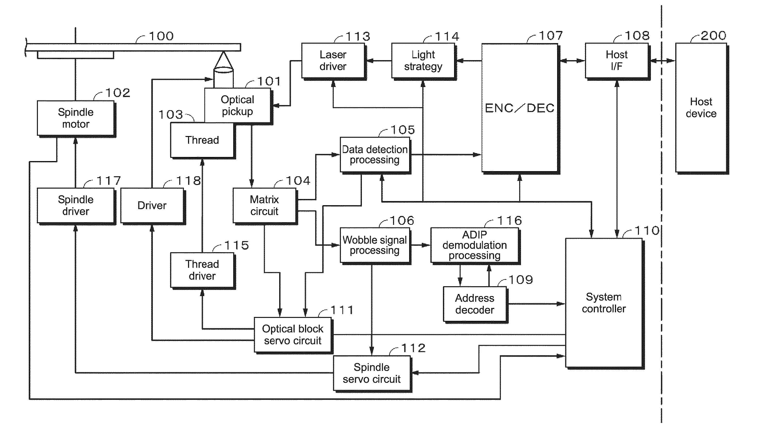
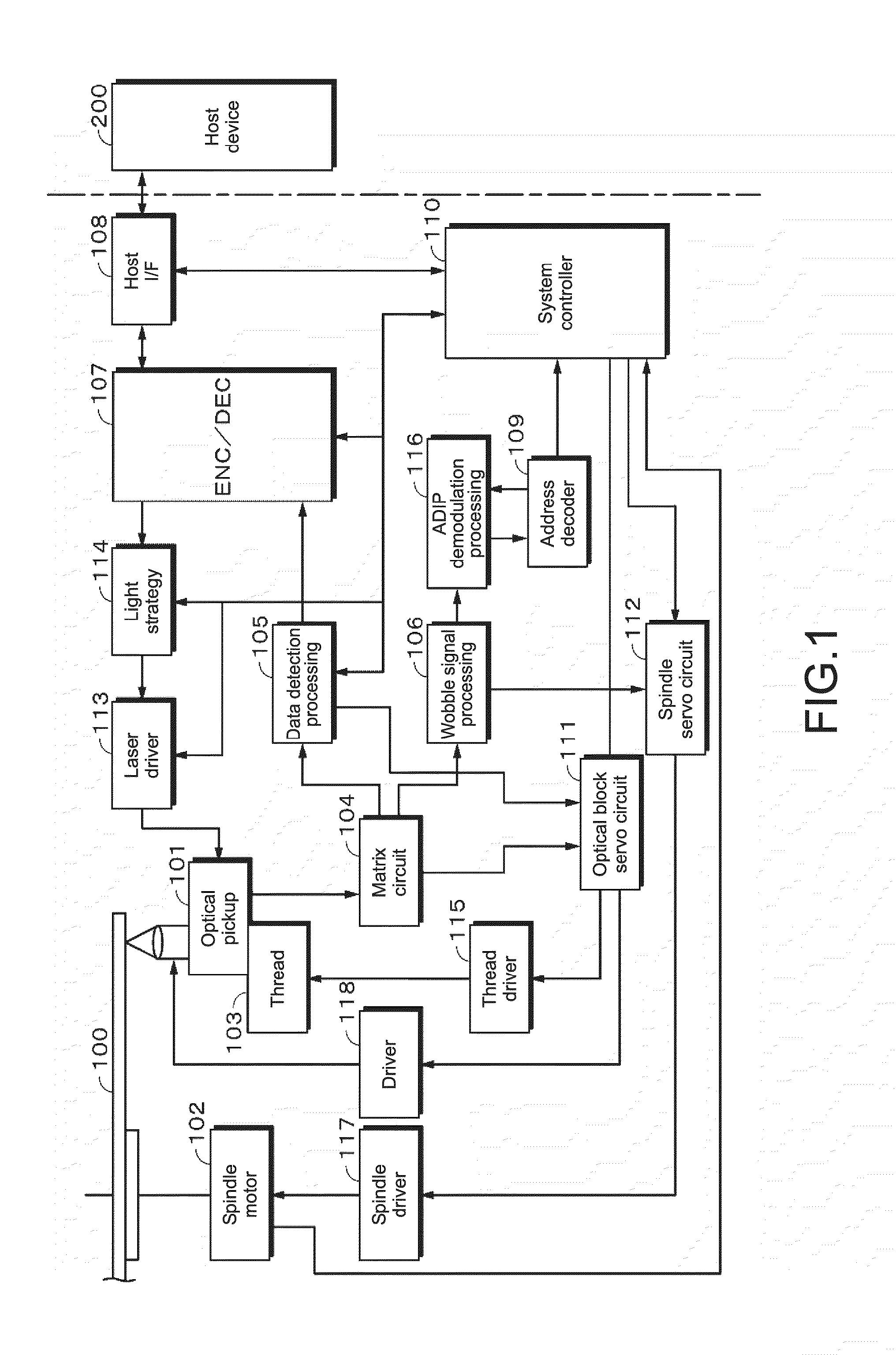
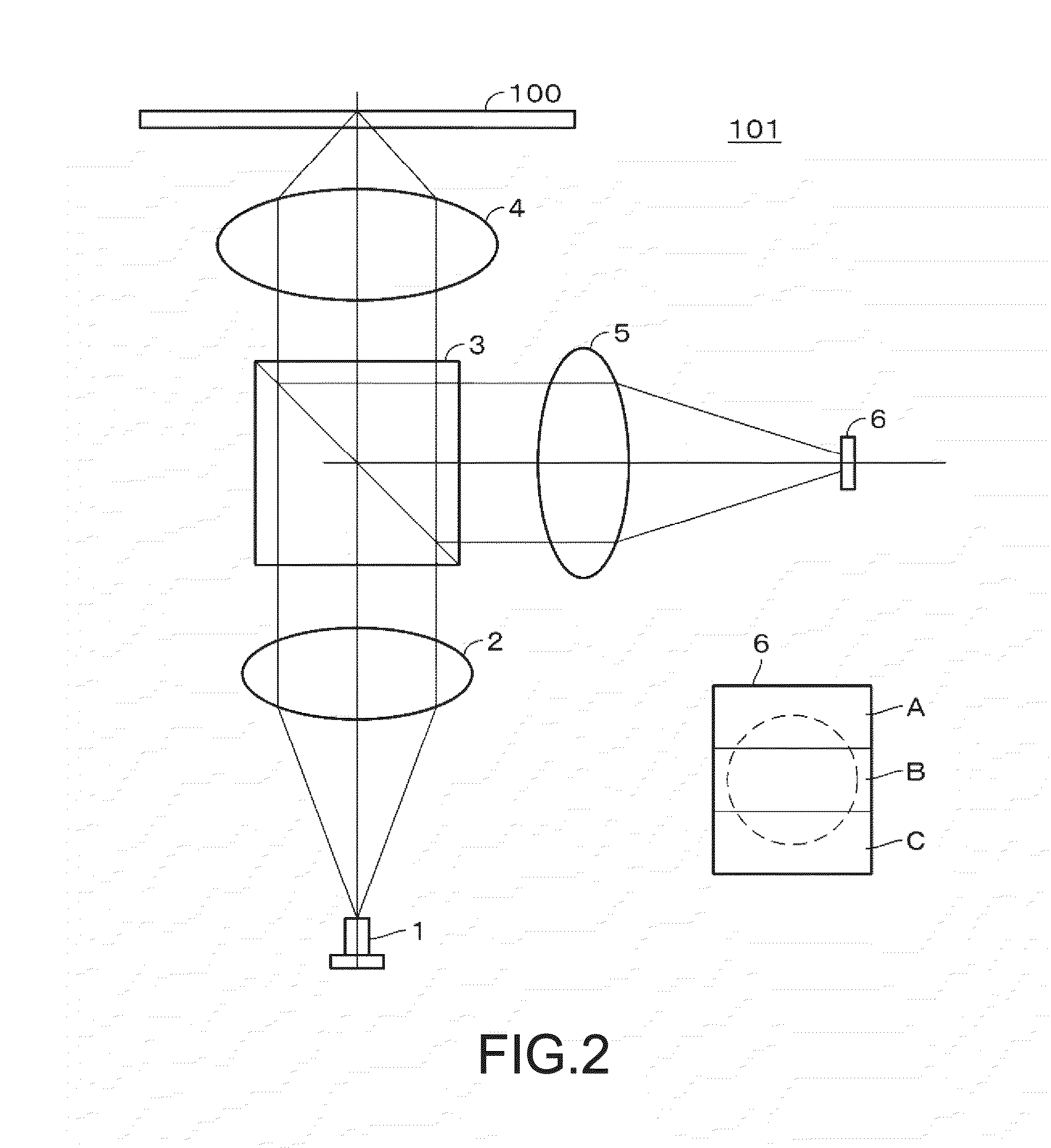
[0037]An optical disc apparatus to which the present disclosure is applied includes an optical pickup 101 for recording and reproducing information on an optical disc 100 as the optical recording medium, and a spindle motor 102 for rotating the optical disc 100, as shown in FIG. 1. To move the optical pickup 101 in a radial direction of the optical disc 100, a thread 103 (feed motor) is disposed.

[0038]As the optical disc 100, a high density optical disc such as a BD (Blu-ray Disc™) can be used. The BD is a high density optical disc having a recording capacity of about 25G bytes on a single layer on one face and about 50G bytes on two layers on one face. According to a BD specification, a light source wavelength is 405 nm and a numerical aperture (NA) of a lens is as great as 0.85 in order to reduce a beam spot diameter. According to a CD specification, a light source wavelength is 780 nm, a NA is 0.45 and a spot diameter is 2.11 μm. According to a ...


PUM

PropertyMeasurementUnit
diameteraaaaaaaaaa
diameteraaaaaaaaaa
spot diameteraaaaaaaaaa

Abstract

An optical medium reproduction apparatus for optically reproducing an optical medium where a plurality of tracks are formed, including: a detection unit for splitting a cross section of a beam returned from the optical medium into a plurality of regions and for forming respective detection signals of a plurality of the regions; a multiple input adaptive equalizer having a plurality of adaptive equalizer units, wherein the respective detection signals of a plurality of the regions are inputted into the plurality of adaptive equalizer units, and the outputs of the plurality of adaptive equalizer units are computed to from equalization signals; a binarization unit for binarizing the equalization signals to provide binary data; and an equalization error computing unit for determining an equalization error from equalization target signals provided based on the binary data from the binarization unit and the equalization signals outputted from the multiple input adaptive equalizer, and providing the adaptive equalizer units with the equalization error as control signals for adaptive equalization.

Description

TECHNICAL FIELD[0001]The present invention relates to an optical medium reproduction apparatus for reproducing an optical medium such as an optical disc, and a method of reproducing an optical medium.BACKGROUND ART[0002]There are two methods for densifying an optical disc. On method is by shortening a channel bit length, i.e., a mark length, in a line density direction. The other method is by narrowing a track pitch. However, when the track pitch is narrowed, information leakage from adjacent tracks (adjacent track cross talk) is increased. There is proposed a method for decreasing the adjacent track cross talk (hereinafter simply referred to a cross talk, as appropriate).[0003]For example, Patent Document 1 describes that a cross talk is cancelled by providing an adaptive equalizer unit with reproduction signals for a track to be reproduced and tracks at both sides of the track to be reproduced and by controlling a tap coefficient of the adaptive equalizer unit.[0004]Patent Documen...

Claims


Application Information

Patent Timeline
Patent Type & Authority Applications(United States)
IPC IPC(8): G11B20/10
CPCG11B20/10212G11B20/10046G11B7/005G11B7/133G11B20/10055G11B7/0943G11B20/24G11B7/0037G11B7/00718
Inventor NISHI, NORIAKASAITO, KIMIHIROSHIRAUSHI, JUNYANAKAO, TAKASHIYAMAMOTO, KENJI
Owner SONY CORP
Why Eureka
Try Eureka