Beam incorporating aluminum extrusion and long-fiber reinforced plastic

a technology of extrusion and plastic, applied in bumpers, paper/cardboard containers, vehicular safety arrangments, etc., can solve the problems of not being able to meet all design goals, no single material or process satisfies all design goals, and aluminum material tends to perform acceptablely under compressive stress but not as well under tensile stress, etc. , to achieve the effect of optimal impact bending strength, high energy absorption properties, and increased manufacturing efficiency

Inactive Publication Date:
View PDF1 Cites 47 Cited by
  • Summary
  • Abstract
  • Description
  • Claims
  • Application Information

AI Technical Summary

Benefits of technology

[0015]An object of the present invention is to construct a beam with metal material (e.g. aluminum) in an optimal location to undergo compression during an impact against the beam, and with polymeric material (e.g. long-fiber-reinforced polymeric material) in an optimal location to undergo tension during the impact, and with adhesive and dissimilar bonded materials in an area of low stress during the impact (i.e. along a neutral plane).
[0016]An object of the present invention is to construct a beam of extruded aluminum and fiber-reinforced polymeric material, and with mechanical fasteners that hold the aluminum and polymeric material together until an adhesive cures and fully bonds abutting / adjacent materials, the fasteners also providing additional retaining strength during an impact in the fully cured beam.
[0017]An object of the present invention is to incorporate mechanical locking and adhesive-enabling features that can be integrally formed when extruding aluminum sections.
[0018]An object of the present invention is to extrude aluminum sections that are open sections (i.e. not closed tubes), thus allowing increased manufacturing efficiency when extruding the aluminum sections, yet providing a beam incorporating the aluminum sections that is a closed section so that, when impacted, it provides optimal impact bending strengths, high energy absorbing properties, high strength-to-weight ratios, high energy-absorption-to-weight ratios, and reduced total mass.

Problems solved by technology

One dilemma is that no single material or process satisfies all design goals.
For example, aluminum has low weight, but is not as strong as high strength steel, nor as light as polymeric material.
Also, aluminum material tends to perform acceptably under compressive stress but not as well under tensile stress.
Aluminum extruding processes can eliminate some manufacturing steps, but extruding processes limit the beam shapes that can be produced, and further limit the types and strengths of aluminum materials that can be used.
Polymeric material has very low weight, but is not as strong as steel nor aluminum.
Also, reinforced polymeric materials tend to provide significantly poorer impact strength than metals, especially when formed into thin walls.
Polymeric materials tend to perform acceptably under tensile stress but not as well under compressive stress.
A subtle but significant design problem is that when a beam is “beefed up” in order to meet government and insurance industry standards, other areas will have “excess” material or will provide an “overkill” of strength and function.
In some words, more material or strength is provided in some areas than is optimally required to meet the standards, thus leading to unnecessarily high cost or weight where “excess” material is located in unnecessary areas.
As a result, that load peaks may not be as sharp.
Thus, bumper beams made of a single material often cannot be optimally designed for particular vehicles' bumper systems in terms of best localized strength properties (which needs vary along a bumper's length), low weight, and maximum value per unit weight and per unit function.

Method used


Image

  • Beam incorporating aluminum extrusion and long-fiber reinforced plastic
  • Beam incorporating aluminum extrusion and long-fiber reinforced plastic
  • Beam incorporating aluminum extrusion and long-fiber reinforced plastic

Examples


Embodiment Construction

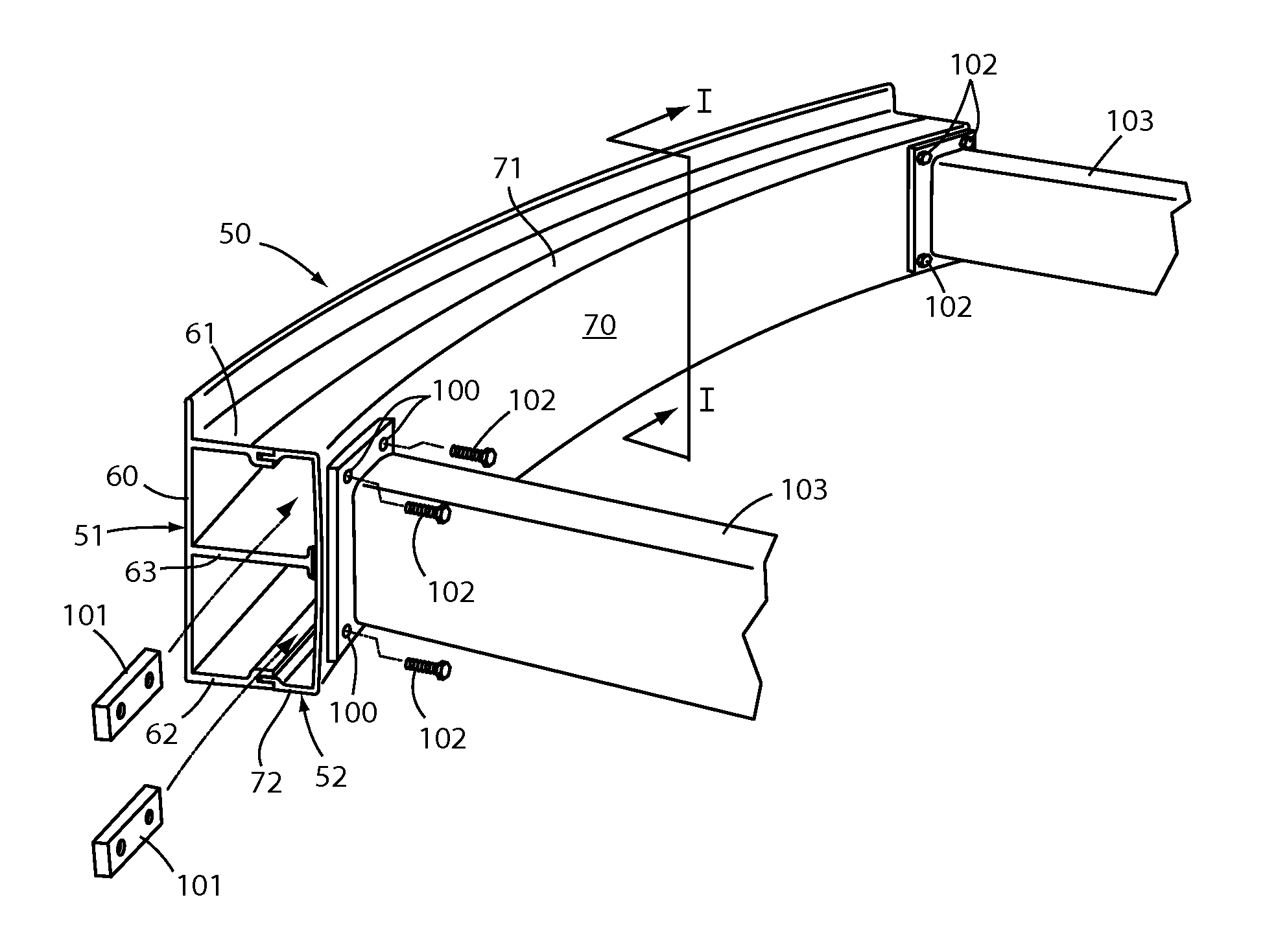
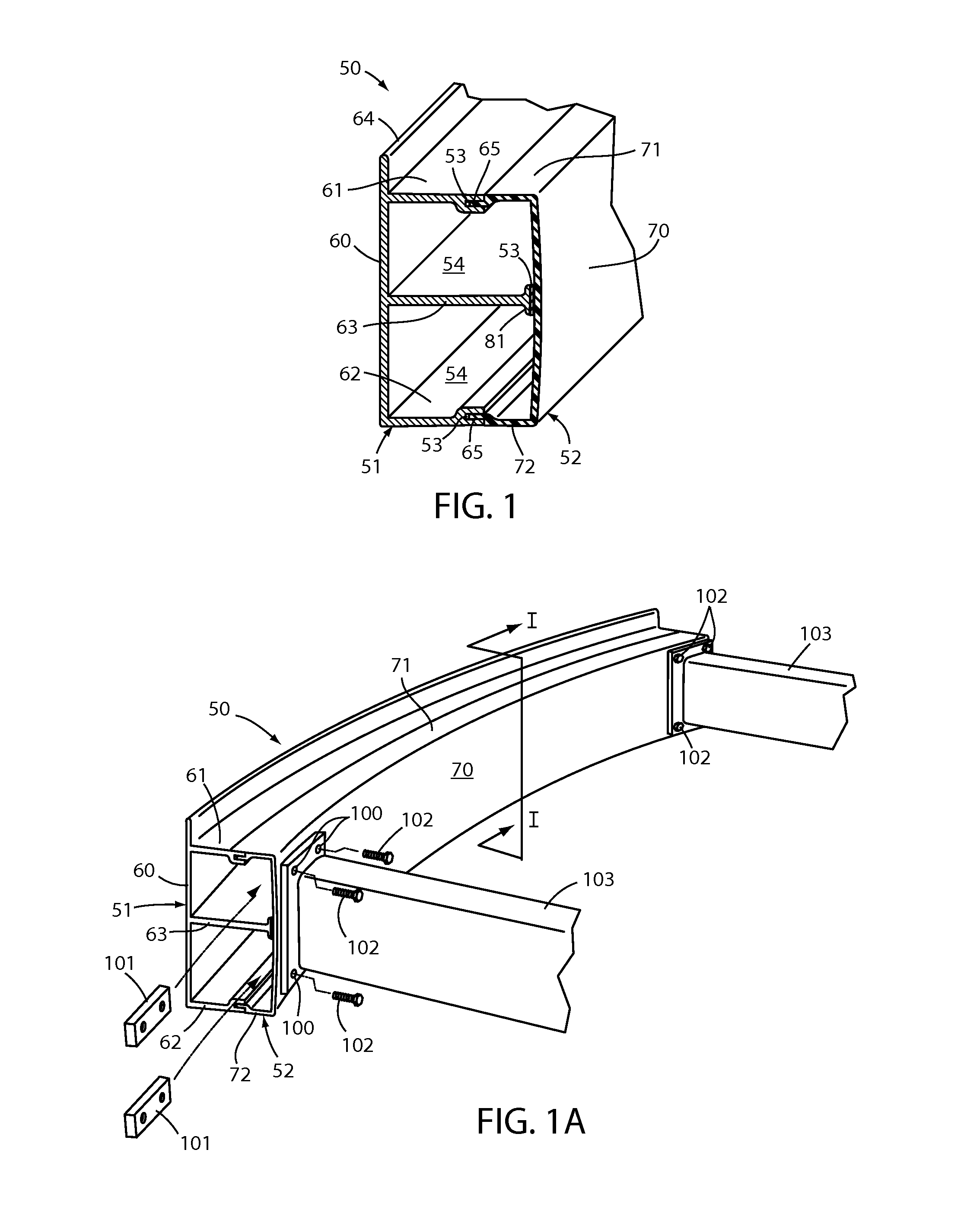
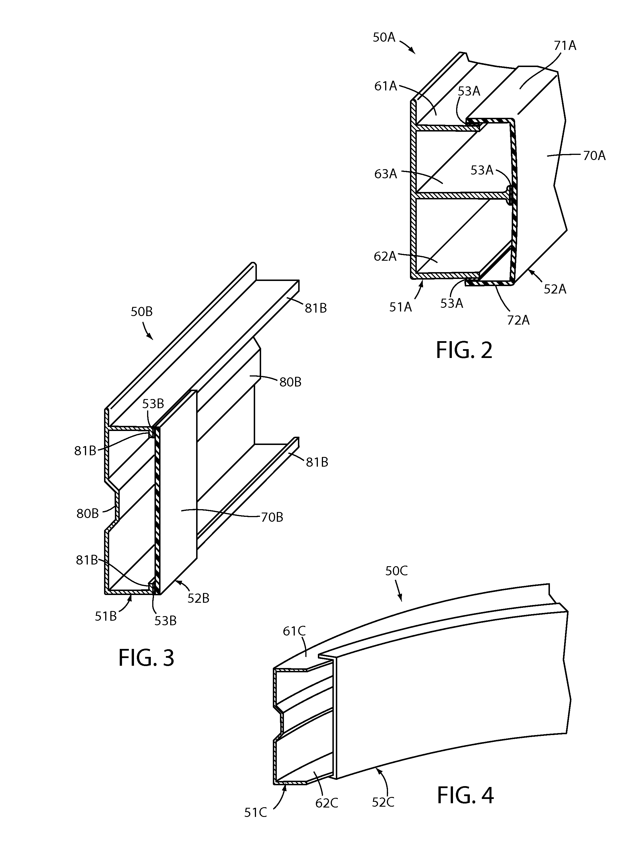
[0024]The present innovative system comprises an impact beam, such as can be used as a bumper reinforcement beam in vehicle bumper systems. The illustrated beam 50 of FIG. 1 bonds a multi-channel-shaped fiber reinforced polymeric (FRP) part 52 to an extruded metal section 51 (e.g. aluminum) using structural adhesive 53, to thus form an impact beam suitable for attachment to vehicle frame rails 104 as a bumper reinforcement beam. The illustrated arrangement includes attachment plate brackets 101 placed inside the beam 50, and fasteners 102 extended through holes 103 in a plate at a front end of the illustrated frame rail tips 104 and extended into threaded holes in the brackets 101. However, it is contemplated that various attachment constructions can be used and are within a scope of the present invention.

[0025]The present innovation focuses / facilitates optimizing beams during design while maintaining flexibility of design, with the beam having optimal properties of: high impact str...


PUM

PropertyMeasurementUnit
lengthaaaaaaaaaa
tensile strengthaaaaaaaaaa

Abstract

A hybrid impact beam, suitable for use as a reinforced impact beam in vehicle bumpers, includes an extruded aluminum section, a fiber reinforced polymeric (FRP) section, and a structural adhesive bonding them together. The components are arranged so that during an impact, the aluminum section experiences compression and receives the direct impact, the FRP section experiences tension, and the adhesive experiences minimal stress by being on a neutral plane of the beam's bending moment. The extruded aluminum beam is preferably extruded as an open section, but becomes a closed section when the polymeric section is attached. The FRP section is preferably a continuous carbon fiber reinforced polymeric section, although different reinforcements can be used. A related method includes bonding an extruded aluminum and fiber-reinforced polymeric section together to form a closed bumper impact beam.

Description

CROSS-REFERENCE TO RELATED APPLICATION[0001]This application claims benefit under 35 USC section 119(e) of U.S. Provisional Patent Application Ser. No. 62 / 087,950 entitled BEAM USING ALUMINUM EXTRUSION AND LONG-FIBER REINFORCED PLASTIC, filed Dec. 5, 2014, the entire contents of which are incorporated herein by reference.BACKGROUND OF THE INVENTION[0002]The present invention relates to impact beams where optimal impact properties and low weight are important, and more particularly relates to a hybrid impact beam constructed from a combination of an extruded aluminum section, fiber-reinforced polymeric material, and adhesive, where the materials are optimally located to manage compressive, tensile, and torsional stress during an impact.[0003]Bumper reinforcement beams for vehicle bumper systems have stringent functional requirements. Low weight is important due to its effect on vehicle gas mileage, but strength and impact properties are important given the government (FMVSS) and insu...

Claims


Application Information

Patent Timeline
Patent Type & Authority Applications(United States)
IPC IPC(8): B60R19/18B23P15/00B60R19/03
CPCB60R19/18B60R19/03B23P2700/50B60R2019/182B60R2019/1853B23P15/00
Inventor MATECKI, JOSEPH R.MALKOWSKI, BRIAN E.
Why Eureka
Try Eureka