Carbonized material production kiln

a carbonized material and kiln technology, applied in the direction of solid fuel combustion, lighting and heating apparatus, combustion types, etc., can solve the problems of large amount of carbonized materials, large volume, and inability to meet the needs of new raw materials, so as to prevent cracking, accelerate carbonization, and long life

Active Publication Date: 2016-06-09
YAMAMOTO BIO CHARCOAL MFG
View PDF0 Cites 1 Cited by
  • Summary
  • Abstract
  • Description
  • Claims
  • Application Information

AI Technical Summary

Benefits of technology

[0018]Adopting the first aspect of the present invention can provide a production kiln characterized by the following. By being loaded with raw materials a moisture percentage of which has been made to be that in an unseasoned wood state a plurality of times from the side of the open ceiling surface, while the production kiln is capable of producing a large amount of carbonized materials in a single step of carbonized material production by pressing an upper surface of the raw materials for carbonization to shut off outside air in conjunction with a film of steam generated during carbonization, in a case such that an exposed surface on a kiln side wall is damaged due to traveling or bumping of the traveling work machine, the production kiln allows recombining the surface of a block being in a cubic shape to thereby enable recombination of up to six faces and is thus excellent in maintainability. Moreover, the block can be prevented from cracking by a difference in thermal expansion because the block is without reinforcing iron, which thus allows providing the production kiln with a long life. Furthermore, by the heat storage / retention member filled in the exhaust space, the temperature in the production kiln can be maintained at a high temperature even during periods of cold temperatures such as the winter season, during rain fall, etc., which allows accelerating carbonization.
[0019]Adopting the second aspect of the present invention enables continuously producing a larger amount of carbonized materials using the plurality of production kilns adjacent to each other via the partition side wall.
[0020]Adopting the third aspect of the present invention eliminates entry of outside air into the combustion device through the exhaust space of a production kiln that is not in the process of carbonization production, which allows efficiently combusting exhaust gas from a production kiln that is performing carbonization production.
[0021]Adopting the fourth aspect of the present invention allows efficiently combusting by the combustion device only exhaust gas from a production kiln that is performing carbonization production.
[0022]Adopting the fifth aspect of the present invention allows combusting exhaust gas generated from a production kiln other than one production kiln using the combustion device provided for the one production kiln.

Problems solved by technology

Now, as methods for making such carbonized materials, carbonized material production kilns provided as movable types are conventionally known (refer to Patent Documents 1 and 2), but there has been a problem that because of being a movable type, the carbonized material production kiln has a small capacity and cannot therefore produce a large amount of carbonized materials at one time.
However, because either type of these performs a step of producing carbonized materials in a closed manner, not only a fire hole and a ceiling cover are required, but a new raw material supply according to a volume reduction is also virtually impossible when raw materials are reduced in volume with carbonized material production, and only raw materials loaded at first can be carbonized, so that there is still a problem in the point of producing a large amount of carbonized materials.

Method used


Image

  • Carbonized material production kiln
  • Carbonized material production kiln
  • Carbonized material production kiln

Examples


first embodiment

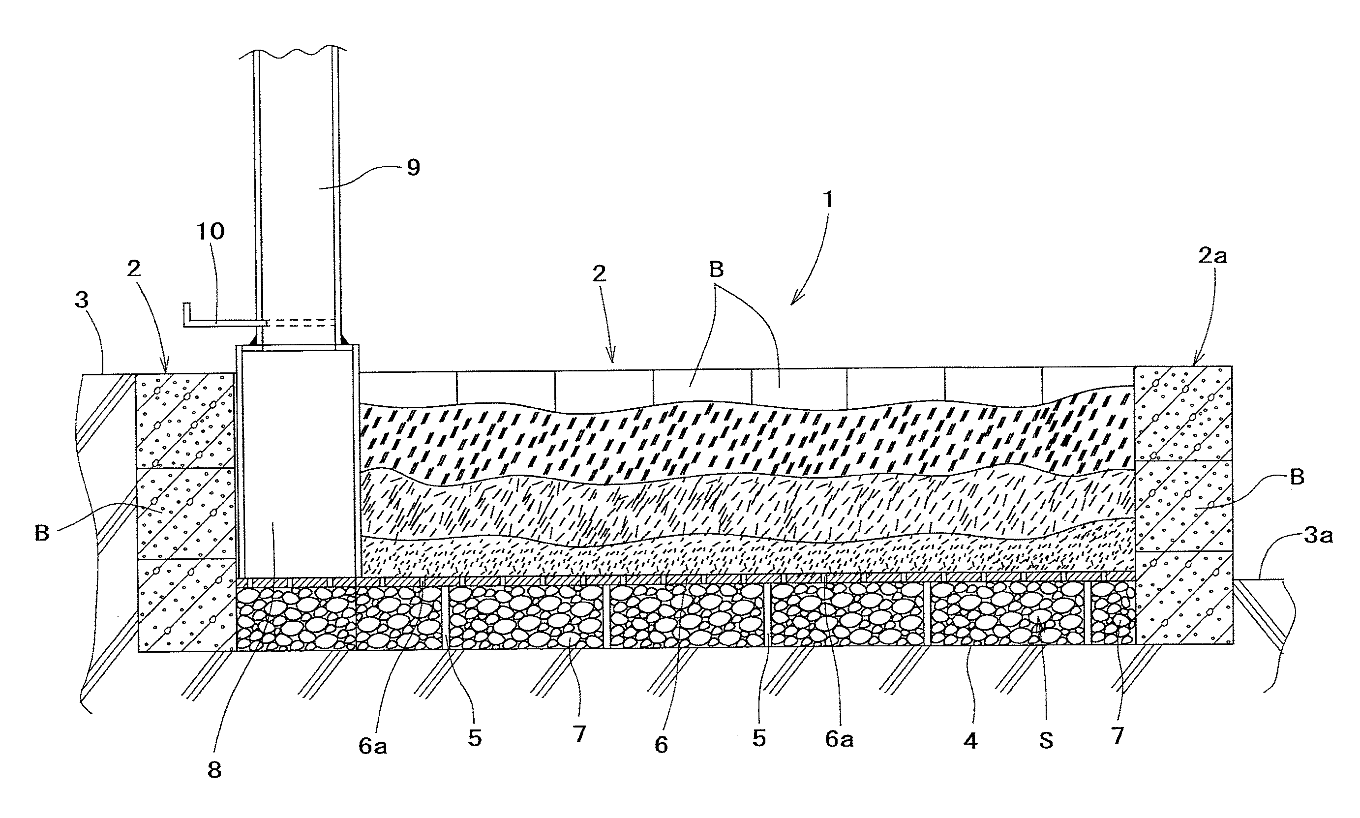
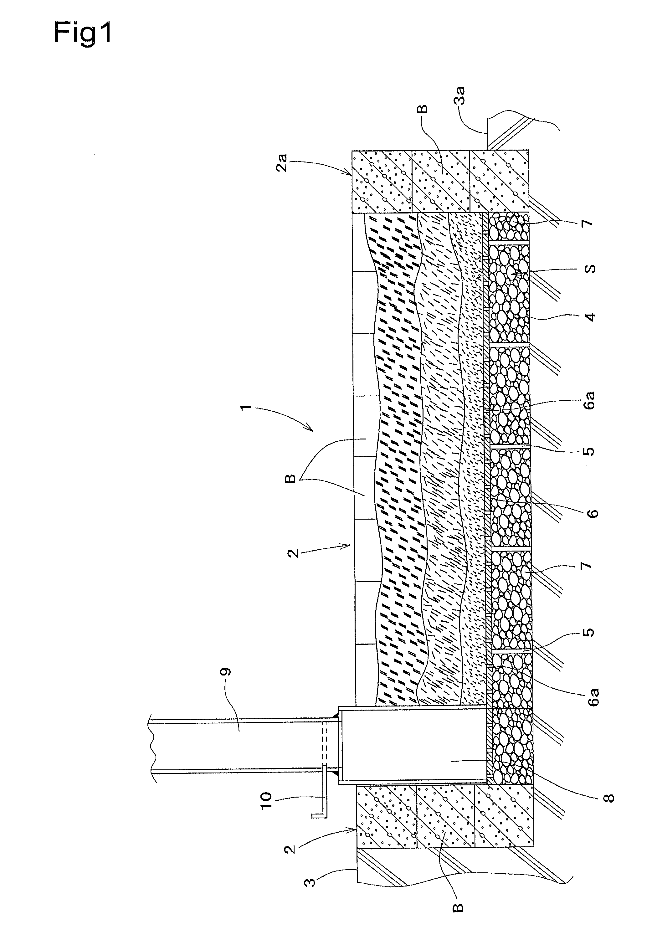
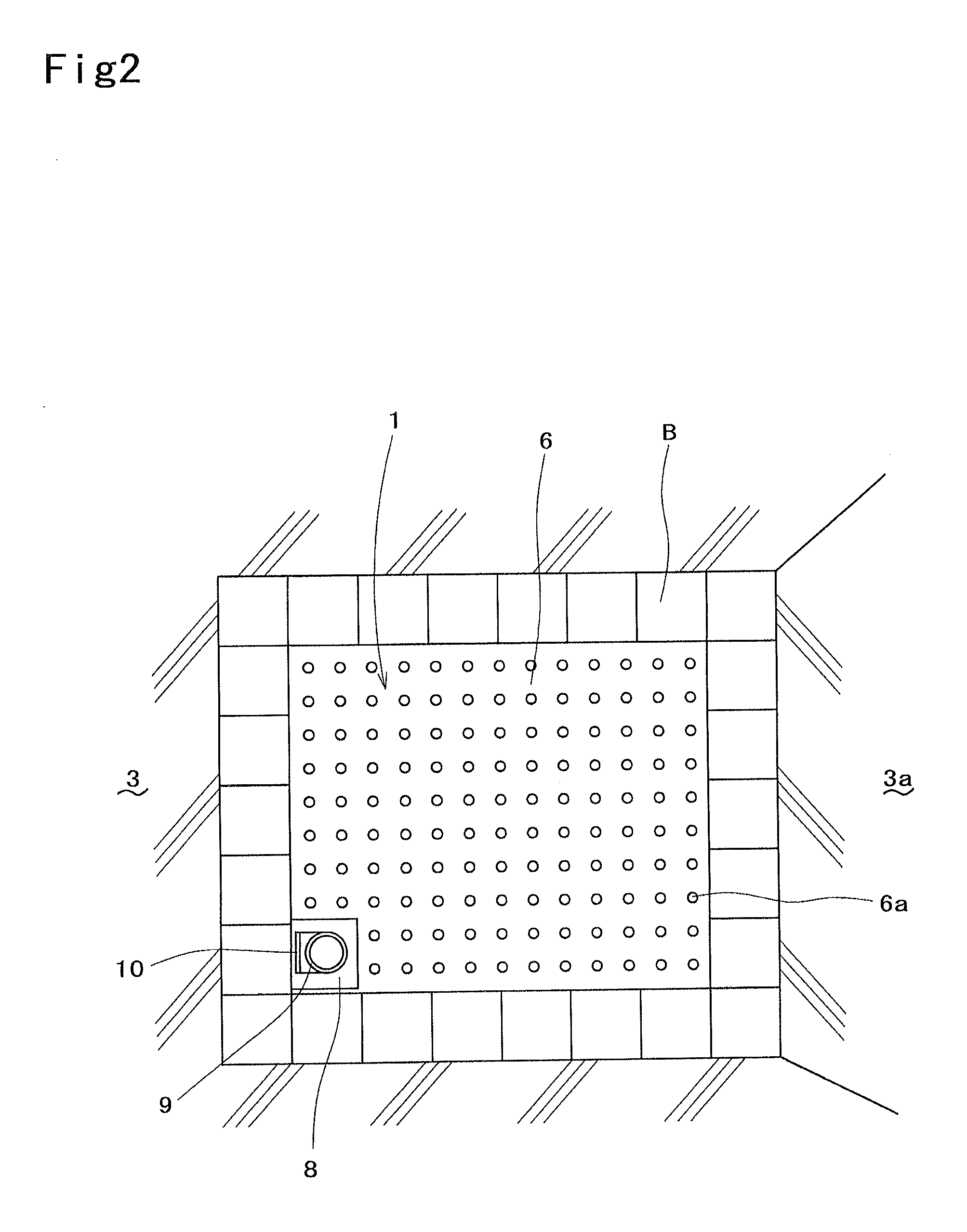
[0032]Next, embodiments of the present invention will be described with reference to the drawings. In the drawings, reference numeral 1 denotes a carbonized material production kiln. The production kiln 1 is open at its ceiling surface, and has side walls 2 and 2a at four peripheral sides formed by stacking solid concrete-made blocks B without reinforcing iron vertically and horizontally. Each block B is in a cubic shape having six square faces on its outer periphery. A first embodiment shown in FIG. 1 and FIG. 2 includes a single production kiln 1, for which the blocks B are stacked in plural numbers in a height direction and front-rear and right-left directions (in the present embodiment, three blocks are stacked in the height direction, and appropriate numbers of blocks are stacked in the front-rear and right-left directions) and side walls 2 and 2a at four peripheral sides of which are formed in a state. Of these side walls 2 and 2a, an outer side surface of at least one side wa...

second embodiment

[0043]In addition, the present invention is of course not limited to the above-mentioned embodiment, and a pair of first and second production kilns 1 and 1a can be provided adjacent to each other as in a second embodiment shown in FIG. 3 to FIG. 6. In this case, a partition wall 11 to provide a partition between the adjacent production kilns 1 and 1a is formed wide by stacking into a plurality of rows (in the present embodiment, two rows) so as to enable a traveling work machine to travel, and such an arrangement allows stably performing a necessary operation using a traveling work machine on the partition wall 11.

[0044]Moreover, in the present embodiment, the first production kiln 1 is provided with a combustion device 8 and the second production kiln 1a is not provided with a combustion device 8, an exhaust space S of the second production kiln 1a and the combustion device 8 are connected to communicate with each other via a ventilation flue 12 provided in lowermost blocks B, and...

third embodiment

[0045]Further, the present invention can also be carried out as in a third embodiment shown in FIG. 7. The present embodiment has an exhaust space S formed like a grid trench 14 in the front-rear and right-left, and a kiln bottom surface 4a in a site without the grid trench 14 is formed with a slight clearance secured with respect to the kiln floor iron plate 6 so as to provide a heat storage / retention function, and a temperature fall in the production kiln 1 is thereby avoided.

[0046]Further, the present invention can also be carried out as one for which production kilns 1 and 1a at four faces are made adjacent to each other in the front-rear and right-left as in a fourth embodiment illustrated in FIG. 8(A), and as one in which a production kiln 1b at one side is large as in a fifth embodiment illustrated in FIG. 8(B), and such combinations are arbitrary.

[0047]Also, in the present invention, as in sixth and seventh embodiments illustrated in FIG. 9(A) and FIG. 9(B), the partition wa...


PUM

PropertyMeasurementUnit
temperatureaaaaaaaaaa
heightaaaaaaaaaa
shapeaaaaaaaaaa

Abstract

To enable a carbonized material production kiln to be maintained in a simple manner when an exposed surface on a side wall of the kiln is cracked, to prevent the kiln from easily cracking by heat to thereby prolong the life of the kiln itself, and to increase heat retention efficiency to thereby increase carbonization efficiency even during periods of cold temperatures such as the winter season. The carbonized material production kiln is formed by stacking cubic concrete blocks each having no reinforcing iron so that recombination of up to six faces of each cubic concrete block becomes possible, wherein a heat storage / retention member such as stones is filled in an exhaust space formed between a kiln floor iron plate and a kiln bottom so as to store heat, thereby preventing a decrease in carbonization efficiency even at cold temperatures.

Description

TECHNICAL FIELD[0001]The present invention relates to a technical field of carbonized material production kiln capable of continuously making a large amount of carbonized materials in a single carbonizing operation step.BACKGROUND ART[0002]Generally, carbonized materials such as wood charcoal, bamboo charcoal, coconut shell charcoal, and palm empty fruit bunch charcoal for which various plants including wood, bamboo, coconut shells, and palm empty fruit bunches have been carbonized have porous structures and exhibit excellent adsorption functions, and therefore have been widely used not only for fuels but also in various industrial fields, without being limited to consumers fields, of moisture absorbing materials, deodorizing materials, water quality improving materials, adsorbing materials, etc. Therefore, providing high-quality carbonized materials having constant adsorbing functions has been demanded. Now, as methods for making such carbonized materials, carbonized material produ...

Claims


Application Information

Patent Timeline
Patent Type & Authority Applications(United States)
IPC IPC(8): C10B53/02C10B47/02
CPCC10B47/02C10B53/02C10B1/02C10B49/02F27D1/003Y02E50/10F23G5/0273F23G2202/103F23G2201/303F23B90/06F23B10/02F23M5/02F23M2700/0053
Inventor YAMAMOTO, AKIO
Owner YAMAMOTO BIO CHARCOAL MFG
Why Eureka
Try Eureka