Device for wavelength combining of laser beams

Active Publication Date: 2016-06-09
TRUMPF LASER GMBH CO KG
View PDF3 Cites 45 Cited by
  • Summary
  • Abstract
  • Description
  • Claims
  • Application Information

AI Technical Summary

Benefits of technology

[0019]An object of the present invention is to provide a device for wavelength coupling with improved properties. This object is achieved according to a first embodiment by a device for wavelength coupling of the type mentioned in the introduction, further comprising: a feedback device arranged in the beam path between

Problems solved by technology

The laser beam emitted from a respective laser diode has an almost diffraction-limited beam quality in the FA direction and has a comparatively poor beam quality in the SA direction, at least for currently known broad stripe emitters.
However, the beam quality in such an overlap is normally inferior to that when the laser beams of a plurali

Method used


Image

  • Device for wavelength combining of laser beams
  • Device for wavelength combining of laser beams
  • Device for wavelength combining of laser beams

Examples


Embodiment Construction

[0106]Identical reference symbols are used in the following description of the drawings for the same components or components with the same function.

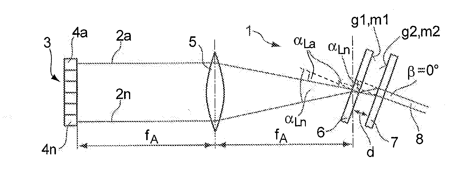
[0107]FIG. 1 shows a device 1 for the wavelength coupling of laser beams 2a . . . 2n with respective different wavelengths λ1 . . . , λn, that are generated by a laser source 3. For generating the laser beams 2a, . . . , 2n the laser source 3 has a corresponding number of laser bars 4a, . . . , 4n that form a vertical stack and which are cooled by a DCB heat sink (not shown) on their rear side. It is evident that laser beams 2a, . . . , 2n, which are generated by a plurality of emitters arranged on a single laser bar, can also be overlapped instead of laser beams 2a, . . . 2n, which are generated by different laser bars, wherein transformation optics (not shown) can be used, as the case may be, to change the orientation of the laser beams 2a, . . . , 2n. The laser beams 2a, . . . , 2n can also be generated by a plurality of single or du...


PUM


Abstract

A device for wavelength coupling of laser beams (2a, . . . 2n) with different wavelengths (λ1, . . . λn), comprising: at least one laser source for generating a plurality of laser beams (2a, . . . , 2n), and an overlapping device for spatial overlapping of the plurality of laser beams (2a, . . . , 2n) for forming an overlapped laser beam with a plurality of wavelengths (λ1 . . . λn). The device has a feedback device arranged between the laser source and the overlapping device for feeding a radiation proportion of the laser beams (2a, . . . , 2n) to be overlapped back to the laser source, the feedback device comprising a partially reflecting angle-dispersive optical element, in particular a partially reflecting diffraction grating. The overlapping device may, for example, be configured as a transmitting or reflecting diffraction grating whose optical properties are adapted to the optical properties of the partially reflecting diffraction grating to overlap the laser beams (2a, . . . , 2n) in an essentially dispersion-free manner.

Description

BACKGROUND OF THE INVENTION[0001]1. Field of the Invention[0002]The present invention relates to a device for wavelength coupling of laser beams with different wavelengths, comprising: at least one laser source for generating a plurality of laser beams, and at least one overlapping device for the spatial overlapping of the plurality of laser beams to form an overlapped laser beam with a plurality of wavelengths.[0003]2. Description of Related Art[0004]A device for the (dense) wavelength coupling of a plurality of laser beams comprises a laser source that generates a plurality of laser beams for overlapping or wavelength coupling. The laser beams are spatially overlapped in an overlapping device and form an overlapped laser beam that has a plurality of wavelengths. Spectrally sensitive elements, for example in the form of edge filters, may be used as an overlapping device. An angle-dispersive optical element is frequently used as an overlapping device. The laser beams striking at dif...

Claims


Application Information

Patent Timeline
IPC IPC(8): G02B27/10H01S3/13H01S3/23G02B27/42G02B27/28H01S3/00G02B27/30
CPCG02B27/1086H01S3/0071H01S3/1305H01S3/1307G02B27/30H01S3/2391G02B27/1073G02B27/4244G02B27/4277G02B27/286G02B27/1006H01S5/005H01S5/4012H01S5/405H01S5/4062H01S5/4087
Inventor NEGOITA, VIORELVETHAKE, THILOKILLI, ALEXANDERTILLKORN, CHRISTOPHSTROHMAIER, STEPHANRIED, STEFFENLI, YUFENGAN, HAIYANBARNOWSKI, TOBIAS
Owner TRUMPF LASER GMBH CO KG
Why Eureka
Try Eureka