
Resistance welding fastener, apparatus and methods for joining similar and dissimilar materials

a technology of resistive welding and fasteners, which is applied in the direction of soldering apparatus, manufacturing tools, capacitors, etc., can solve the problems of aluminum cracking during the riveting process, affecting mechanical strength and corrosion resistance, and each of these processes may be more challenging, so as to increase the resistance of the fastener

Active Publication Date: 2016-06-16
HOWMET AEROSPACE INC
View PDF4 Cites 34 Cited by
  • Summary
  • Abstract
  • Description
  • Claims
  • Application Information

AI Technical Summary

Benefits of technology

This patent is about a new type of fastener that has a projection on its shaft that increases its resistance to being pulled out of a weld. The fastener is designed to have a cap with at least one rib that makes it harder for the cap to be deformed. These improvements make the fastener more durable and reliable.

Problems solved by technology

Direct welding between aluminum and other materials is not commonly employed due to intermetallics generated by the aluminum and the other materials, which negatively affect mechanical strength and corrosion resistance.
Each of these processes may be more challenging than steel-to-steel resistance spot welding (RSW).
For example, when high strength aluminum (above 240 MPa) is coupled to steel using SPR or another sheet of aluminum, the aluminum can crack during the riveting process.
FSJ is not widely employed in the automotive industry since joint properties (primarily peel and cross tension) are low compared to SPR.
Similar considerations pertain to FBJ and FDS, e.g., FDS is typically applied from a single side and requires alignment with a pilot hole in the sheet to be fastened, complicating assembly and adding cost.

Method used


Image

  • Resistance welding fastener, apparatus and methods for joining similar and dissimilar materials
  • Resistance welding fastener, apparatus and methods for joining similar and dissimilar materials
  • Resistance welding fastener, apparatus and methods for joining similar and dissimilar materials

Examples


Embodiment Construction

[0148]The present application incorporates U.S. Provisional Application No. 61 / 839,478, entitled, Apparatus and Method For Joining Dissimilar Materials, filed Jun. 26, 2013, U.S. application Ser. No. 14 / 315,598, entitled, Apparatus and Method For Joining Dissimilar Materials, filed Jun. 26, 2014, U.S. Provisional Application No. 61 / 839,473, entitled, Resistance Welding Fastener, Apparatus and Methods, filed Jun. 26, 2013, U.S. application Ser. No. 14 / 315,698, entitled, Resistance Welding Fastener, Apparatus and Methods, filed Jun. 26, 2014 and U.S. Provisional Application No. 61 / 934,951, entitled, Resistance Welding Fastener, Apparatus and Methods, filed Feb. 3, 2014, by reference in their entirety herein.

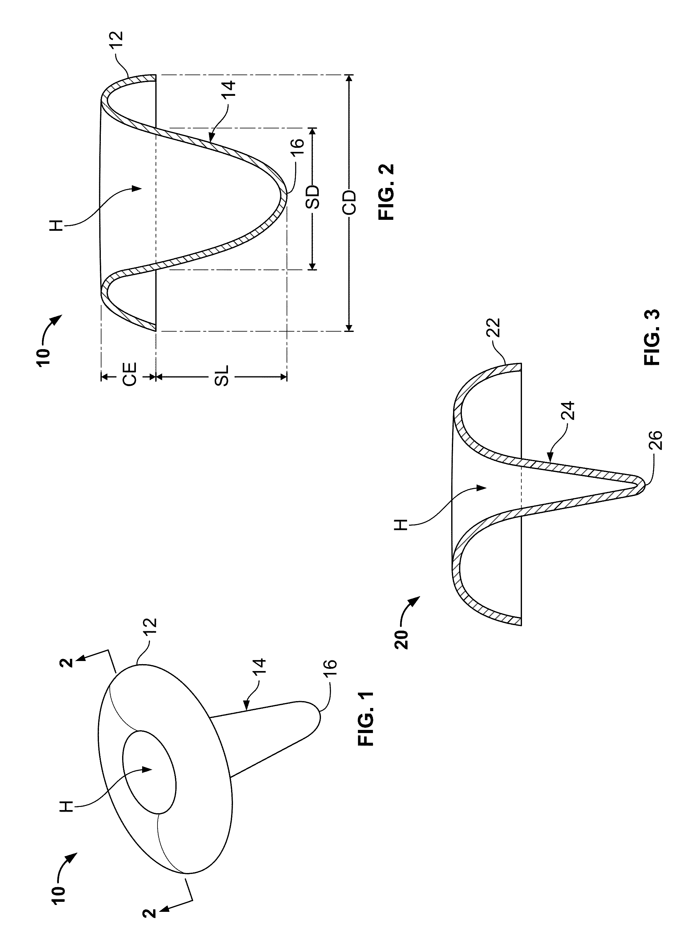
[0149]FIGS. 1 and 2 show a fastener 10 having a peripheral cap 12 and a tapered shaft 14 that has a bluntly pointed end 16 opposite to the cap 12. An internal hollow H extends through the cap 12 and into the shaft 14. The fastener 10 may be made from a conductive metal, e.g., steel...


PUM

PropertyMeasurementUnit
Lengthaaaaaaaaaa
Thicknessaaaaaaaaaa
Diameteraaaaaaaaaa

Abstract

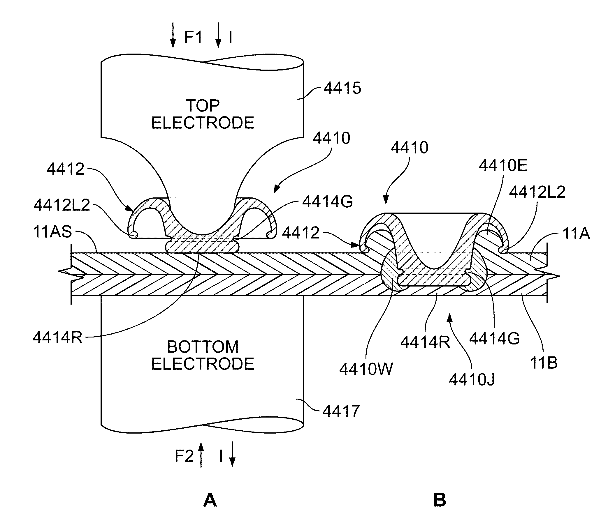
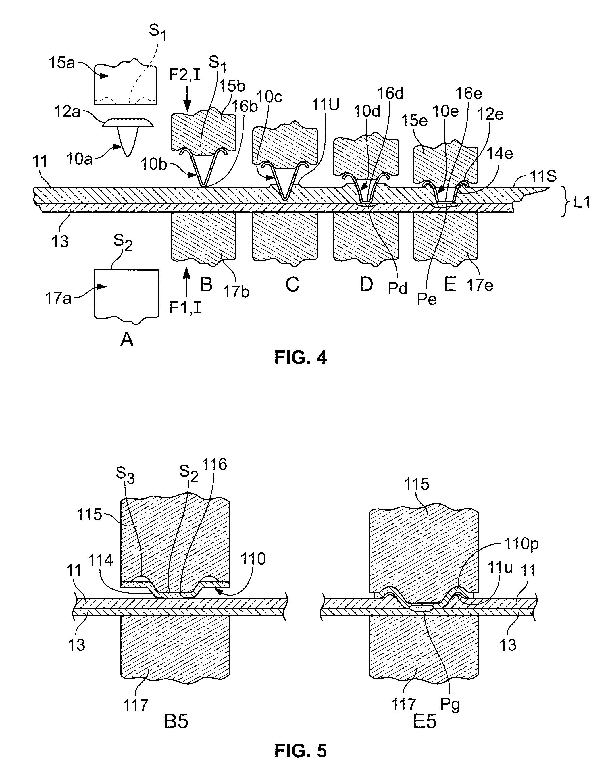
An apparatus and method for fastening layers of non-ferrous alloys, like aluminum, magnesium and copper utilizes a steel fastener and a spot welding machine. The fastener and metals are stacked and the heat from the welder's electric current softens the lower melting point aluminum allowing the fastener to penetrate the aluminum. A weld zone between the fastener and the various layers creates an internal weld. The fastener has a rough shaft that is coated by the molten weld zone and is hard to withdraw on solidification. Layers of non-conductive materials like plastics and ceramics may also be affixed to a conductive layer using a fastener made from a compatible material that extends through a pilot hole and welds to or penetrates a conductive layer. The fastener may have projections that initially reduce contact area with the stack.

Description

CROSS REFERENCE TO RELATED APPLICATIONS[0001]The present application claims the benefit of U.S. provisional patent application No. 62 / 091,980, filed Dec. 15, 2014 and entitled, Resistance Welding Fastener, Apparatus and Methods For Joining Similar and Dissimilar Materials, which is incorporated by reference herein in its entirety.FIELD[0002]The present invention relates to fasteners, fastening apparatus and methods for fastening parts and more particularly, for fastening metals, including dissimilar metals.BACKGROUND[0003]Various fasteners, apparatus and methods for joining and assembling parts or subunits are known, such as welding, riveting, threaded fasteners, etc. In some instances, there is a need to cost effectively join aluminum parts, subunits, layers, etc., to other parts, subunits, layers, etc. made from other materials, such as steel (bare, coated, low carbon, high strength, ultra high strength, stainless), titanium alloys, copper alloys, magnesium, plastics, etc. and / or ...

Claims


Application Information

Patent Timeline
IPC IPC(8): B23K11/30B23K11/20
CPCB23K11/20B23K11/3009B23K11/11B23K2103/10B23K2103/18B23K11/0053B23K11/0066B23K11/18B23K11/185B23K35/0288F16B5/08B23K2101/38B23K2103/12B23K2103/15
Inventor SPINELLA, DONALD J.BERGSTROM, DANIEL
Owner HOWMET AEROSPACE INC
Learn More