Tip clearance control for turbine blades

a turbine blade and tip clearance technology, applied in the direction of pump control, machines/engines, non-positive displacement fluid engines, etc., can solve the problems of blade tip clearance reduction, sfc also rises, mismatch in radial expansion, etc., to optimise the thermal responsiveness of the system, reduce unnecessarily large turbine tip clearance, and increase power

Active Publication Date: 2016-06-16
ROLLS ROYCE PLC
View PDF2 Cites 13 Cited by
  • Summary
  • Abstract
  • Description
  • Claims
  • Application Information

AI Technical Summary

Benefits of technology

[0046]In this manner the selective actuation of the at least one valve may serve as a “switch” to allow or prevent, as the case may be, a flow of air of the predetermined temperature from the feed source to flow through the impingement apertures and onto the casing to effect its heat-transfer (in some embodiments) thereto. Thus, the control device may be configured to selectively actuate the at least one valve only when such heating of the casing is required, e.g. upon beginning, or during, a transient operating condition or stage of an overall flight profile in which the engine is run at increased power.
[0047]When the at least one valve is closed, the corresponding airflow from the feed source through the impingement apertures and onto the casing may thus be at least partially closed. However even in this configuration in some embodiments (especially those in which a pair of carrier walls, including the radially outermost one having the impingement apertures therein, are provided and define therebetween one or more chambers, e.g. a cooling chamber) it may be advantageous to maintain at least a partial airflow path from the space radially outward of the impingement apertured carrier wall and radially inward of the casing and into a said cooling (or other) chamber. Such a maintained airflow path may usefully be provided via one or more holes or conduits in an axially rearmost end of the carrier segment.
[0048]However, it is to be understood that, if desired or necessary, it is possible within the scope of the preceding embodiments for a partial or minor level of airflow from the feed source through the impingement apertures and onto the casing may be maintained at e.g. substantially all times, even outside such transient enhanced-power engine operating conditions, in order to help optimise the thermal responsiveness of the system and the reduction of unnecessarily large turbine tip clearances in any given stage of an overall flight profile. This may for example be useful particularly in the case of shroudless turbine blades.

Problems solved by technology

Accordingly, as tip clearance increases, SFC also rises, which is disadvantageous.
The turbine casing also expands as it heats up, but typically there is a mismatch in radial expansion between the disc / blades and the casing.
Specifically, the blades will normally expand radially more quickly than the casing, thereby reducing the blade tip clearance and potentially leading to rubbing (or re-rubbing) as the tips of blades come into contact with the interior of the casing, until the casing itself heats up and expands sufficiently to increase the tip clearance again back to an optimum distance.
In practical forms this known system shown in FIG. 2 typically employs a thin tinware sheet as the discrete impingement plate 50, which is not only very difficult to assemble, but also leads to significant problems in terms of air sealing and position control, since thin continuous sheet material typically has a much quicker thermal reaction time than the engine casing material itself, which may lead to buckling and thus making the impingement distance between it and the casing much harder to control for optimum impingement performance.
Leakage around the impingement plate 50, leading to compromised engine efficiency, may also be a practical problem.
A disadvantage of this known system, however, is that the dedicated inboard duct is constituted by an additional component that adds weight, cost and build complexity to the overall arrangement.

Method used


Image

  • Tip clearance control for turbine blades
  • Tip clearance control for turbine blades
  • Tip clearance control for turbine blades

Examples


Embodiment Construction

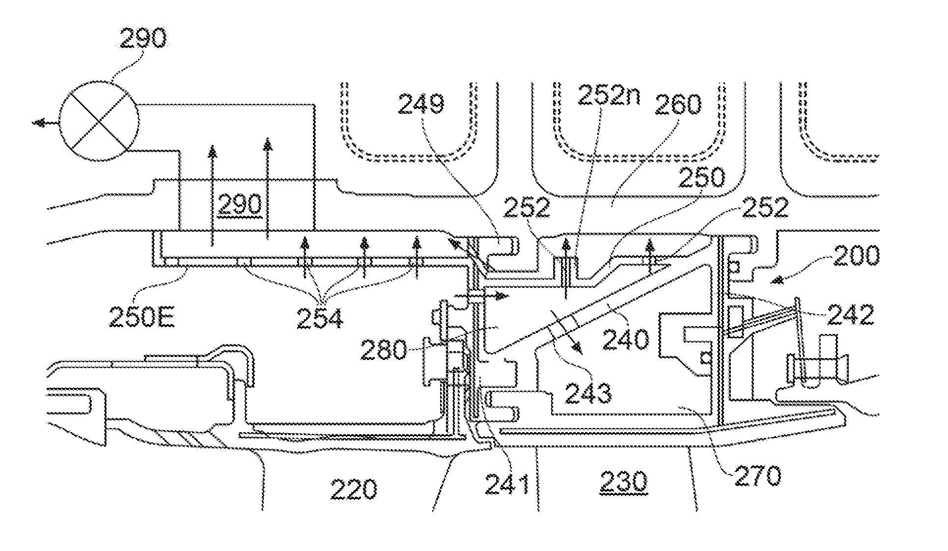
[0061]Referring firstly to FIGS. 3(a) and 3(b) (FIGS. 1 and 2 having already been described in the context of the prior art), here there is shown a first embodiment of the system of the invention, as applied to a HP section of a gas turbine engine, which may be any type of gas turbine engine. In the illustrated arrangement the engine casing 160 and carrier segment 100 are located generally radially outwardly of turbine blades (shown merely schematically as) 130 and HP nozzle guide vanes (NGV's) 120. Also shown are flap seal 148, and a mounting hook or rail 149. The latter has been moved into a relatively more radially outboard location in comparison with many known arrangements, in order to allow an integrally formed undulating carrier wall 140, comprising a series of equi-spaced sinusoidal (or other wave function) corrugations 146, to be accommodated so that the elongate axially oriented peak regions or lands of each corrugation 146 are positioned at a generally uniform and equal s...


PUM


Abstract

An engine includes circumferentially spaced turbine blades radially inward a casing and circumscribed by a carrier section having segments, each having a carrier wall radially inward the casing and radially outward the turbine blades. The wall has one or more portions facing the casing. At least one of the portions has one or more impingement apertures for air passage of a predetermined temperature from a feed source into impingement onto the casing. The segments are radially inward the casing and radially outward the turbine blades, with the portions of their respective walls facing the casing. A method of controlling the gas turbine engine turbine casing temperature includes: passing air of a predetermined temperature from a feed source through the apertures in the one or more portions and into impingement on the casing; and optionally exhausting the air impinged onto the casing from a space between the segment and the casing.

Description

TECHNICAL FIELD[0001]This invention relates to the control of tip clearance of rotating blades within a gas turbine engine by controlling the temperature of the turbine casing. More particularly it relates to methods of controlling the temperature of the turbine casing using arrangements comprising novel carriers for carrying the turbine blade track liner segments, and to the novel carriers themselves and carrier segments for forming such carriers.BACKGROUND OF THE INVENTION AND PRIOR ART[0002]FIG. 1 of the accompanying drawings is a schematic representation of a known aircraft ducted fan gas turbine engine 10 comprising, in axial flow series: an air intake 12, a propulsive fan 14 having a plurality of fan blades 16, an intermediate pressure compressor 18, a high-pressure compressor 20, a combustor 22, a high-pressure turbine 24, an intermediate pressure turbine 26, a low-pressure turbine 28 and a core exhaust nozzle 30. A nacelle 32 generally surrounds the engine 10 and defines the...

Claims


Application Information

Patent Timeline
Patent Type & Authority Applications(United States)
IPC IPC(8): F01D11/24F01D25/28F01D25/24F01D5/12F01D25/14
CPCF01D11/24F01D5/12F01D25/14F01D25/24F01D25/28F05D2270/20F05D2240/24F05D2240/14F05D2260/201F05D2260/30F05D2270/07F05D2220/32
Inventor JONES, SIMON LLOYD
Owner ROLLS ROYCE PLC
Why Eureka
Try Eureka