
Solar Photovoltaic Power Generation Panel Mount

a photovoltaic and panel mount technology, applied in the direction of heat collector mounting/support, pv power plants, lighting and heating apparatus, etc., can solve the problems of large thickness of the support pillar, difficulty in securing sufficient wind-pressure resistance strength, etc., to improve visual quality, easy temporary assembly of vertical bars, and reduce external appearance

Inactive Publication Date: 2016-06-16
SUNRAIL
View PDF0 Cites 19 Cited by
  • Summary
  • Abstract
  • Description
  • Claims
  • Application Information

AI Technical Summary

Benefits of technology

The solar photovoltaic power generation panel mount described in this patent has several technical effects. Firstly, it allows for easy and uniform adjustment of the position and height of the supporting portions, even if some concrete foundations are uneven. Secondly, it allows for the adjustment of the mount frame to be made even if the concrete foundations are reached a floating state due to surface erosion or other factors. Thirdly, it provides a simple structure for positional adjustments in the up-down and left-right directions. Fourthly, it allows for the use of a horizontal bar that can be added even if the mount frame is greatly enlarged. Fifthly, it allows for the efficient construction of the mount frame with high dimensional accuracy without requiring frequent positional correction. Overall, the panel mount provides improved performance and ease of installation.

Problems solved by technology

In a structure in which an upper end of each support pillar is connected to an intermediate position of a vertical bar of a mount frame as in the former patent literature, the solar battery array in the direction of its short side is arranged to be supported by one support pillar, and therefore, disadvantageously, the support pillar has been required to be greatly thickened from the viewpoint of load resistance, and, constructionally, this structure has been easily effected by the shock of an earthquake, and has had difficulty in securing sufficient wind-pressure-resistance strength at a place easily beaten by a strong wind because of, for example, a landform, and has had strict restrictions on an installation place.

Method used


Image

  • Solar Photovoltaic Power Generation Panel Mount
  • Solar Photovoltaic Power Generation Panel Mount
  • Solar Photovoltaic Power Generation Panel Mount

Examples


Embodiment Construction

[0052]Embodiments of a solar photovoltaic power generation panel mount according to the invention will be hereinafter described in detail with reference to the drawings.

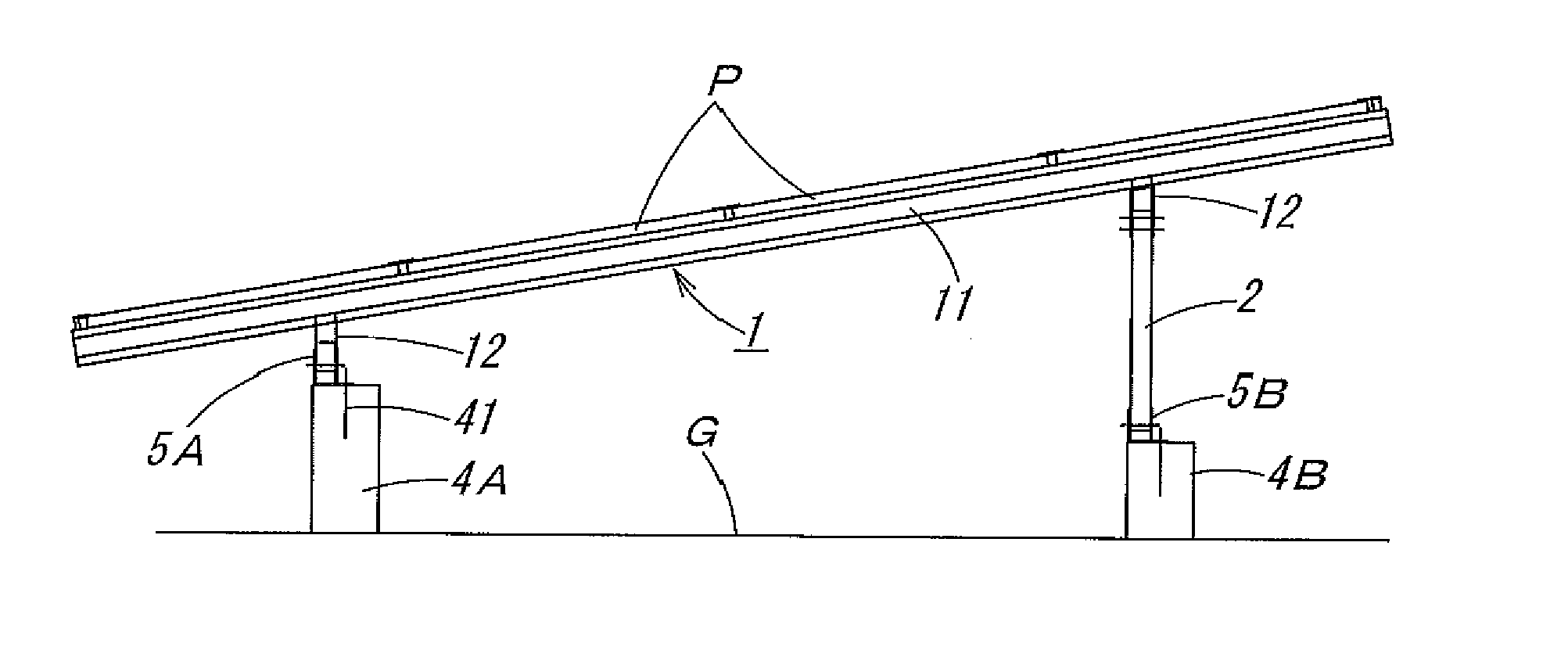
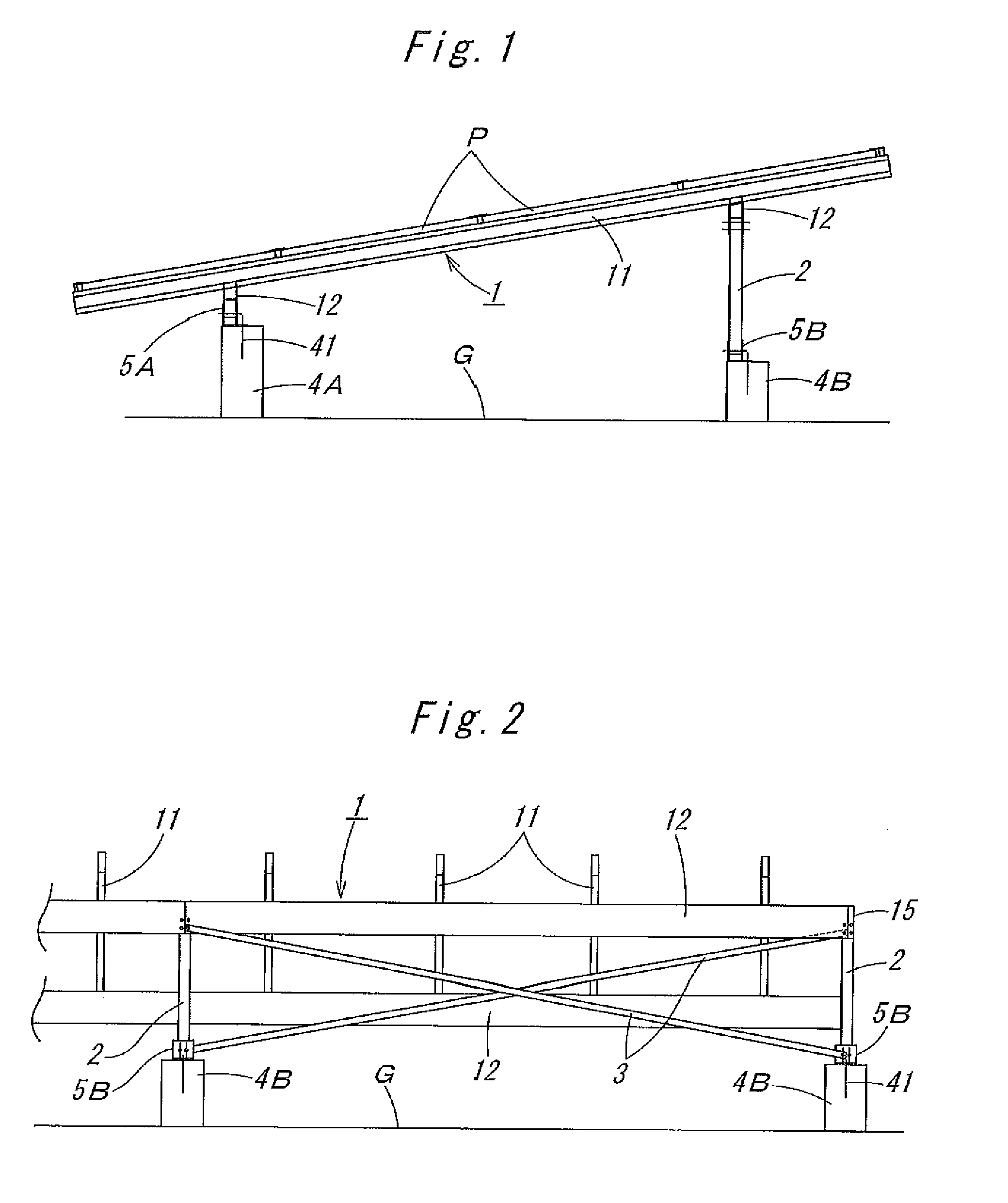
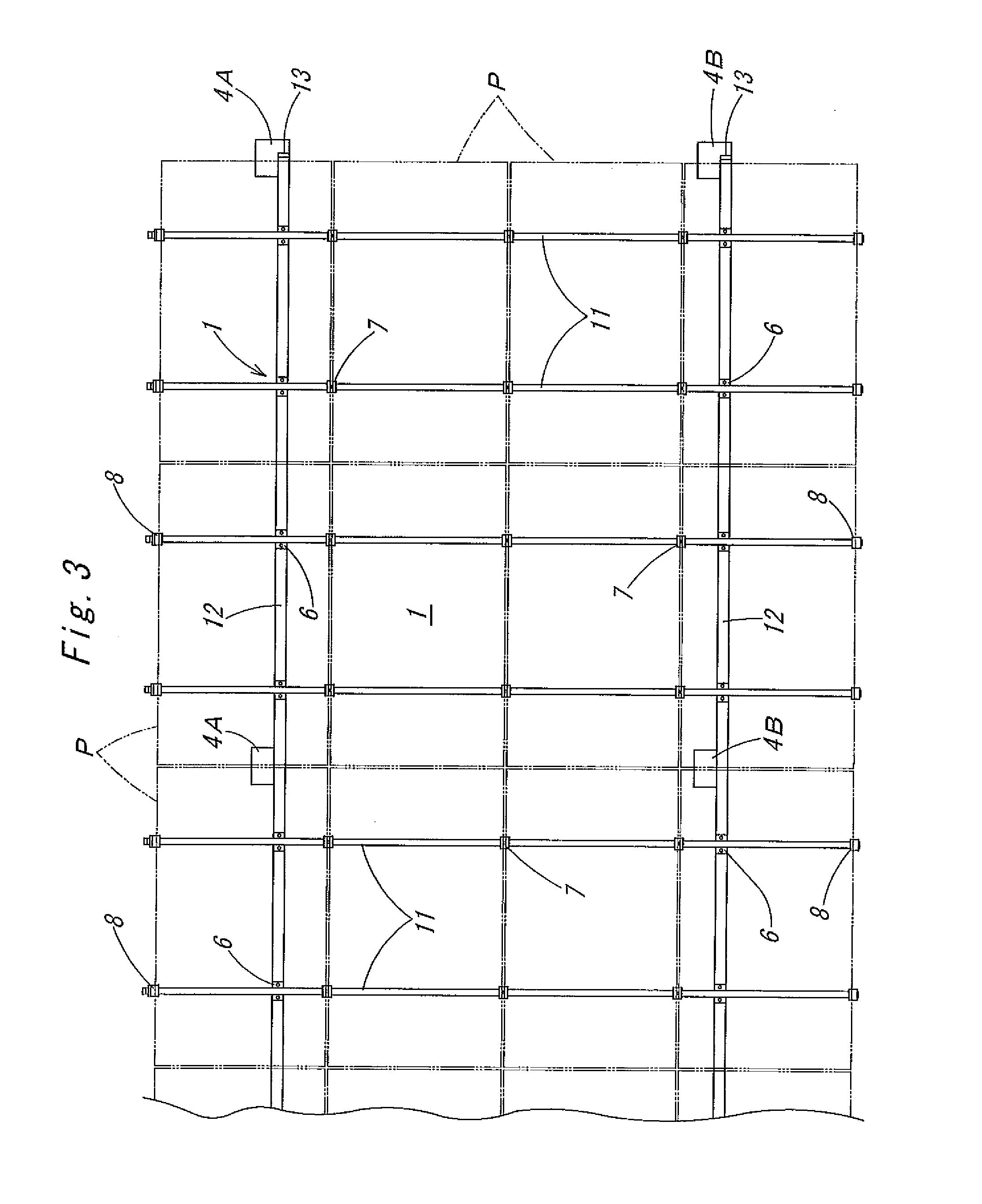
[0053]In a solar photovoltaic power generation panel mount shown in FIG. 1 to FIG. 3, a mount frame 1 that is inclined forwardly and downwardly is constructed on prism-shaped concrete foundations 4A and 4B on the front and rear sides, respectively, that are spaced with a predetermined interval therebetween in the right-left direction, and solar photovoltaic power generation panels P, each of which is rectangular long in the right-left direction and the number of which is four in each row in the front-rear direction and is four or more columns in the right-left direction, are flatly arranged and attached onto the mount frame 1, and a solar battery array is formed of all these solar photovoltaic power generation panels P. The inclination angle of the mount frame 1 shown in the figures is set at 10°.

[0054]In the mount f...


PUM


Abstract

A solar photovoltaic power generation panel mount has a solar photovoltaic power generation panel attached to a mount frame having a plurality of vertical and horizontal bars connected in a grid-like manner. Concrete foundations project upwardly from a mount installation surface at predetermined intervals in a right-left direction under front and rear sides of the mount frame, and the mount frame is supported by the concrete foundations so as to be positionally adjustable in the up-down and right-left directions by mounting brackets fastened to a top of each of the concrete foundations.

Description

FIELD OF THE INVENTION[0001]The present invention relates to a solar photovoltaic power generation panel mount in which a solar photovoltaic power generation panel is installed on a mount frame having a plurality of vertical and horizontal bars connected together in a grid-like manner.BACKGROUND OF THE INVENTION[0002]In recent years, from the viewpoints of environmental protection, resource saving, CO2 reduction, etc., large-scale solar photovoltaic power generation facilities have spread which are called a “mega solar” or a “giga solar” and in which many solar battery arrays are arranged side by side on the ground including flat land and inclined land or on a deck such as the roof of a building. However, generally, a solar battery array, which is formed by arranging a plurality of solar photovoltaic power generation panels (solar battery modules) in a flat manner so as to have its short side of several meters and its long side of from several meters to several tens of meters, is gr...

Claims


Application Information

Patent Timeline
Patent Type & Authority Applications(United States)
IPC IPC(8): H02S20/10H02S20/23
CPCH02S20/10Y02E10/47F24J2/5232H02S20/23F24S2025/807F24S25/65F24S25/617F24S25/70F24S25/636F24S25/12Y02E10/50Y02B10/10
Inventor HIROSE, NORIOKATOH, FUMIO
Owner SUNRAIL
Learn More