
Plasma processing apparatus and operation method thereof

a technology of processing apparatus and plasma, which is applied in the direction of coating, coating, and plasma technique, and achieves the effect of high accuracy ap

Active Publication Date: 2016-06-23
HITACHI HIGH-TECH CORP
View PDF3 Cites 11 Cited by
  • Summary
  • Abstract
  • Description
  • Claims
  • Application Information

AI Technical Summary

Benefits of technology

The patent invention provides a plasma processing apparatus and method that can accurately evaluate the state of the inner walls of the processing chamber where light passes through. This is achieved by obtaining highly accurate data on the light incident on the chamber surface from outside the chamber and the light that has passed through the chamber surface. The invention also reduces noise caused by reflected light from the chamber surface, which can interfere with accurate measurement of the deposit film. Overall, this leads to increased yield of the plasma processing apparatus.

Problems solved by technology

These conventional techniques cause problems because the techniques do not sufficiently consider the following points.
The surface of the inner wall of a processing chamber inside a vacuum chamber after start or the operation of a plasma processing apparatus used for mass production of semiconductor devices are typically worn down owing to the interaction between the member of the surface of the inner wall and plasma, or, onto these surfaces, compounds formed by chemical combination between the member of the surface and gas in the plasma or the processing chamber adhere and deposit Furthermore, there is a case where compounds formed by a reaction in the plasma or on a surface of a sample deposits on the surface of the inner wall having been worn down by the above two causes.

Method used


Image

  • Plasma processing apparatus and operation method thereof
  • Plasma processing apparatus and operation method thereof
  • Plasma processing apparatus and operation method thereof

Examples


modified example

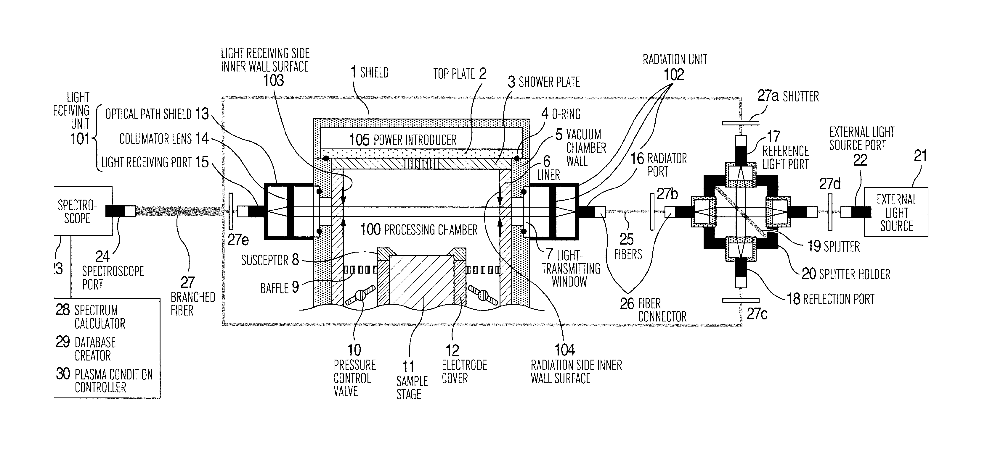
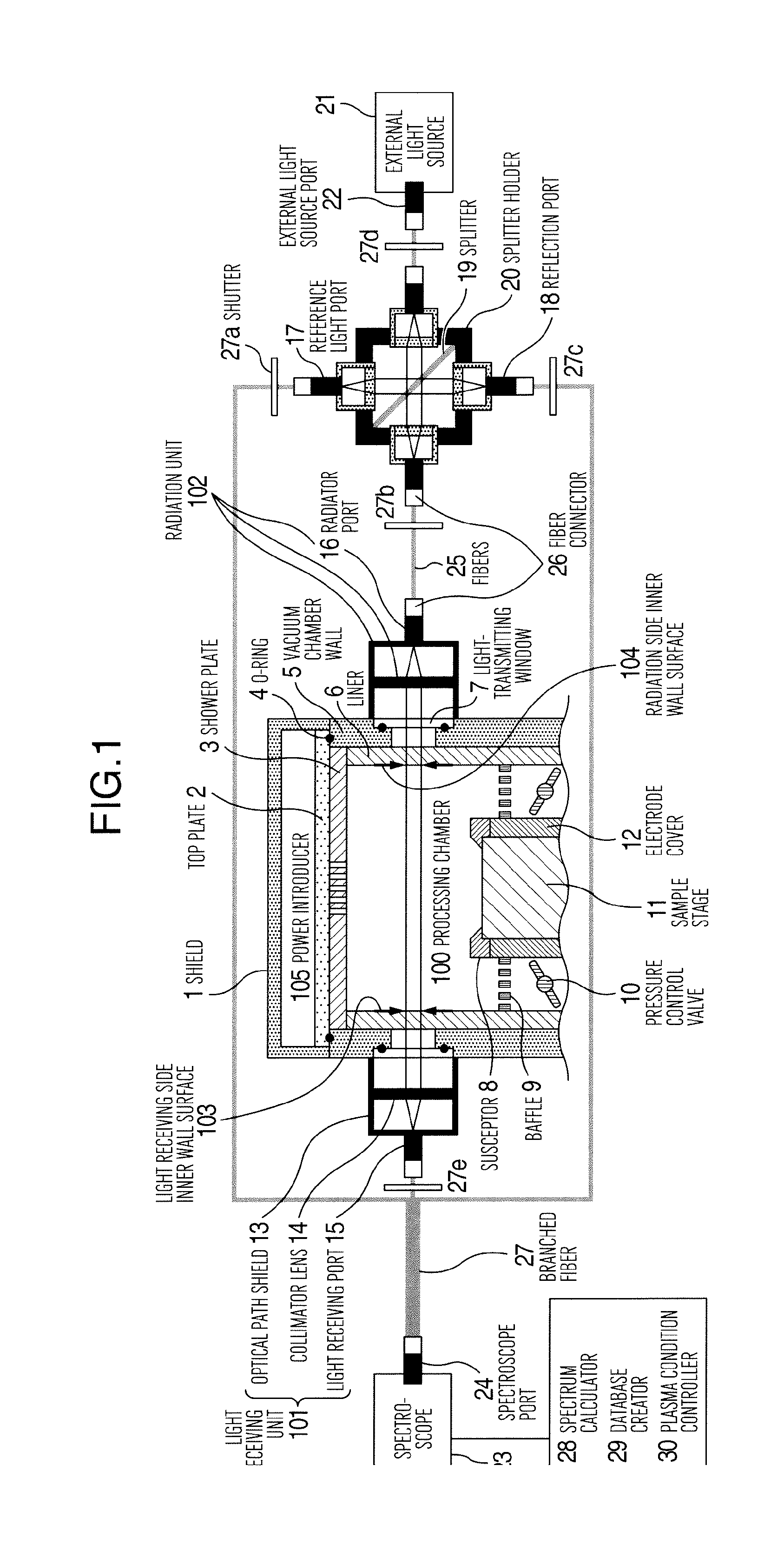
[0201]Next, a modified example of the above embodiment is described with reference to FIGS. 12 to 15. FIG. 12 is a longitudinal sectional view schematically showing an overview of a configuration of a plasma processing apparatus according to a modified example of the embodiment shown in FIG. 1.

[0202]The plasma processing apparatus according to this example detects the variations in the film of accretion formed on the surface of the inner wall of the liner 6 arranged in the processing chamber 100 during wafer processing, or in the condition of the coating film formed for the sake of protecting the inner wall before and after the processing. Configuration elements shown in FIG. 12, except for an optical absorbing unit 450, the branched fiber 27, and the deposit film 400, are equivalent to those described in the embodiment shown in FIG. 1. Consequently, the description on the elements is omitted unless specific description is required.

[0203]In this example, the optical absorbing unit 4...


PUM

PropertyMeasurementUnit
surface roughnessaaaaaaaaaa
diameteraaaaaaaaaa
diameteraaaaaaaaaa

Abstract

A plasma apparatus of processing a wafer disposed in a processing chamber using plasma includes one window, another window, a light receiving unit, a light source, and an optical branching unit which is disposed between the light source and the other window, branches light emitted by the light source to an optical path toward the processing chamber and an optical path in other direction, and reflects light in the processing chamber from the other window, and a detection unit which detects the light having been emitted from the plasma and received by the light receiving unit using one branched light and other branched and reflected light. The apparatus processes the wafer according to a condition for the processing which is adjusted based on a result of the detection.

Description

BACKGROUND OF THE INVENT ON[0001]The present invention relates to a plasma processing apparatus that processes a substrate-like sample, such as a semiconductor wafer, arranged in a processing chamber disposed in a vacuum chamber using plasma formed in the processing chamber, and a method of operating the plasma processing apparatus, and in particular to a plasma processing apparatus that adjusts the sample processing using a result of detecting light from the processing chamber, and a method of operating the plasma processing apparatus.[0002]In order to improve the performance of a semiconductor device, nanometer-level processing accuracy is required in a stage of processing a film structure having multiple film layers that include a mask layer and a film layer to be processed. The mask layer is preliminarily formed on a wafer surface to form circuits of the device on the surface of the substrate-like sample, such as a semiconductor wafer, by means of plasma etching. Furthermore, fo...

Claims


Application Information

Patent Timeline
Patent Type & Authority Applications(United States)
IPC IPC(8): C23C16/513
CPCC23C16/513H01J37/32917H01J37/32926H01J37/32972H01J37/3299H01L21/02315H01L21/0234H01L21/3065H01L21/32136H05H1/46
Inventor OHMORI, TAKESHISATOU, DAISUKEUSUI, TATEHITOINOUE, SATOMIMAEDA, KENJI
Owner HITACHI HIGH-TECH CORP
Learn More