Drive control apparatus for electric motor
- Summary
- Abstract
- Description
- Claims
- Application Information
AI Technical Summary
Benefits of technology
Problems solved by technology
Method used
Image

Examples
first embodiment
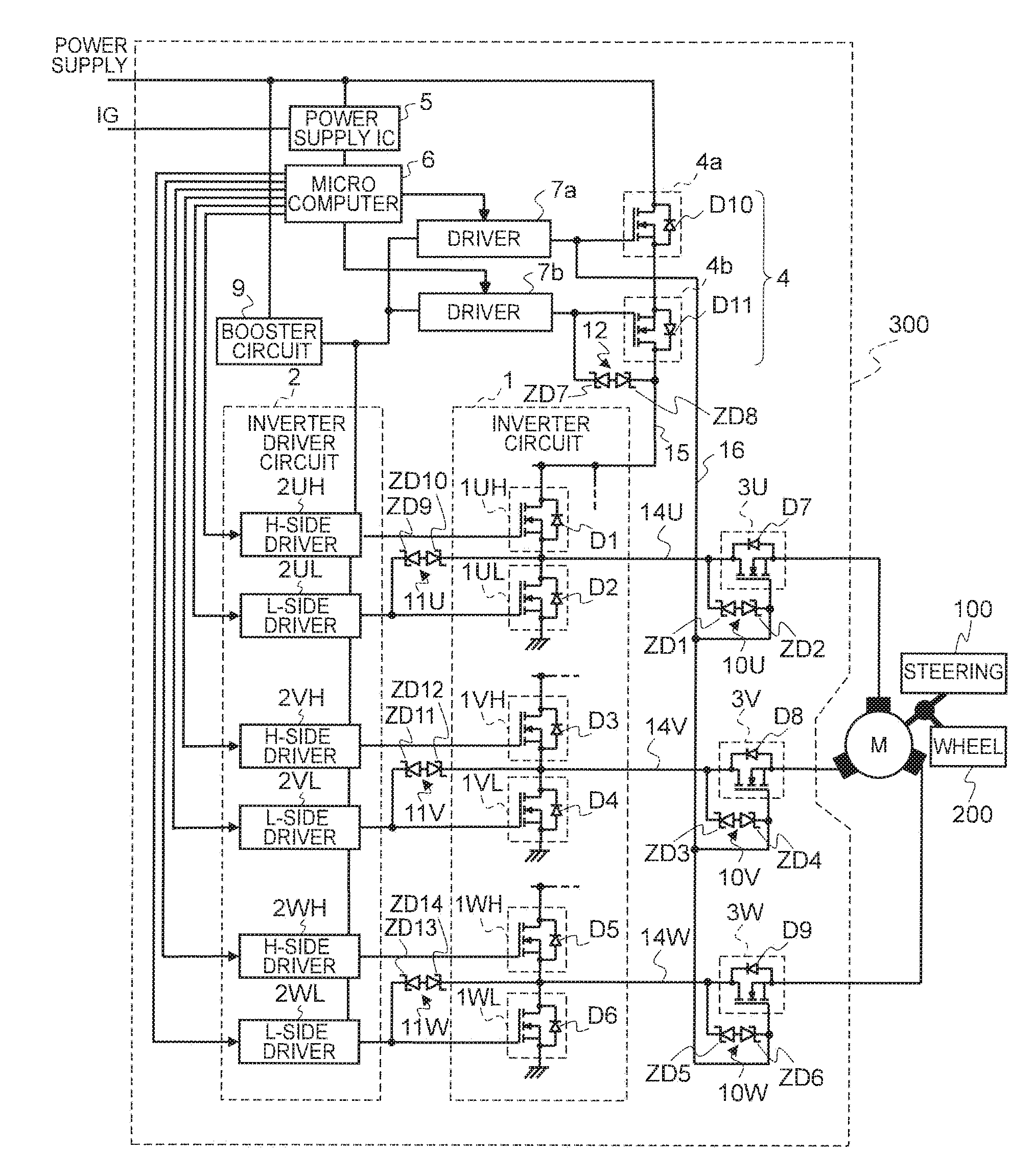
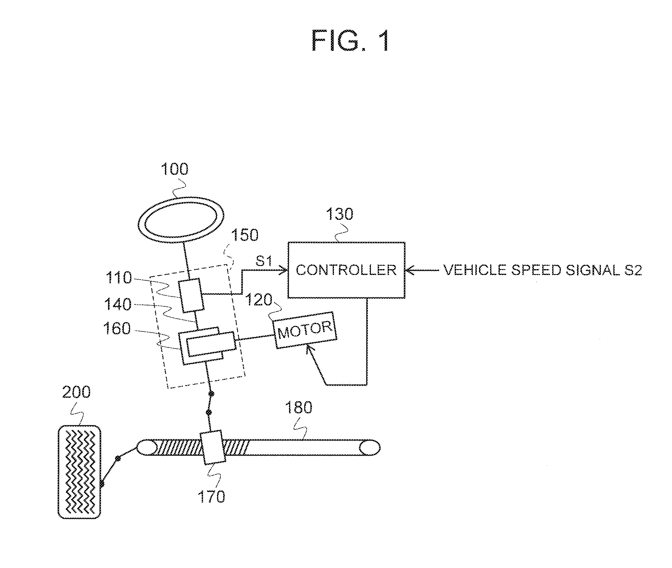
[0022]Next, the circuit configuration of an electric power steering controller according to a first embodiment of the present invention will be described with reference to FIG. 2. In FIG. 2, the assist motor in the EPS system illustrated in FIG. 1 is controlled by a control unit as the controller. Assist motor 120 and controller 130 in FIG. 1 are made to correspond to an electric motor M and a control unit 300, respectively, to supply steering torque signal S1, vehicle speed signal S2, and the like to a microcomputer 6 in control unit 300 (not illustrated). Then, electric motor M is driven by microcomputer 6 via an inverter driver circuit 2 serving as a drive circuit and an inverter circuit 1 to generate a steering assist force according to a traveling state.
[0023]Control unit 300 is configured to further include phase relays 3U, 3V, 3W, power supply relays 4 (a powering cutoff relay 4a and a regeneration cutoff relay 4b), a power supply IC 5, drivers 7a, 7b of a discrete structure ...
second embodiment
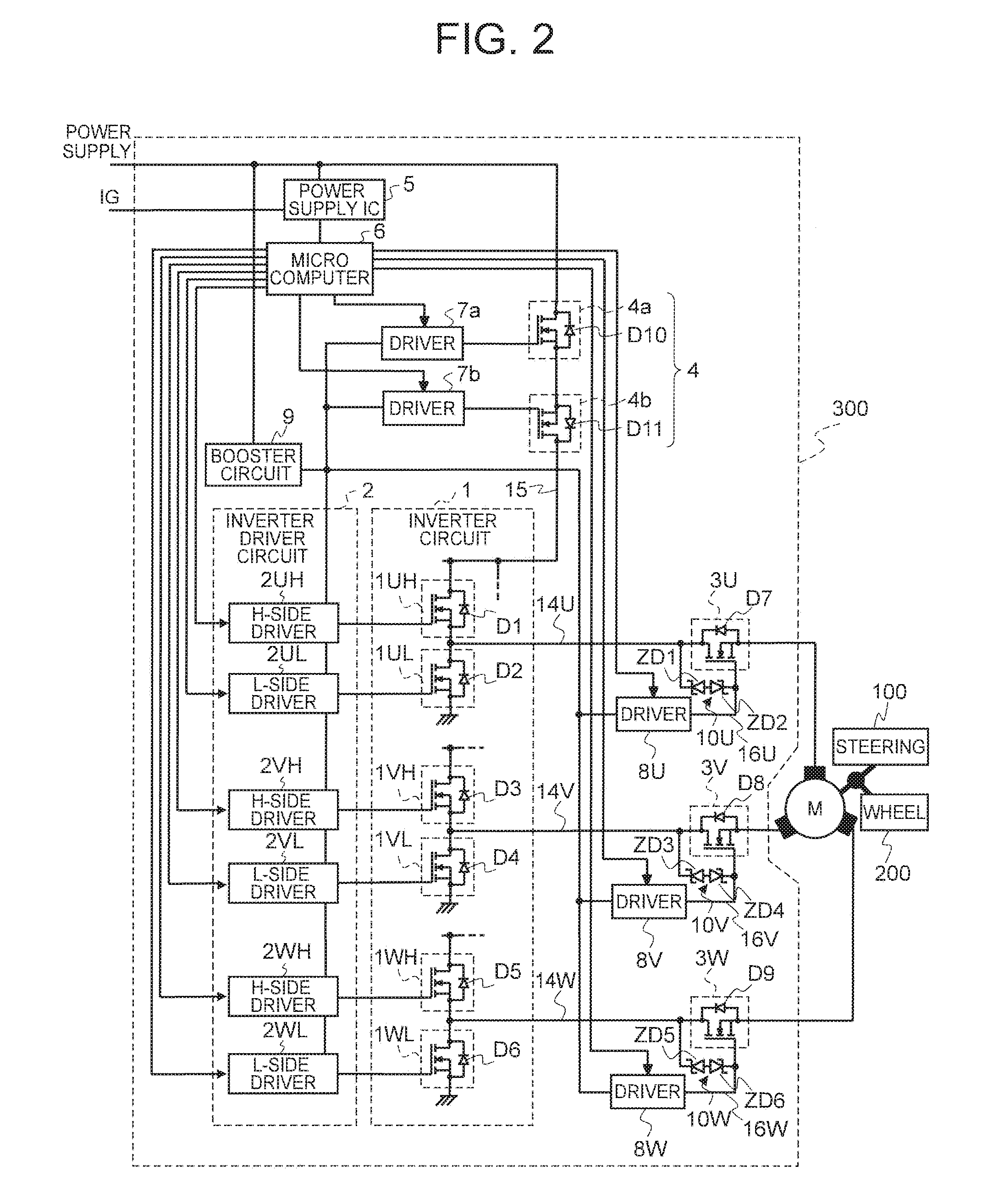
[0068]In the first embodiment described above, drivers 8U, 8V, 8W respectively corresponding to phase relays 3U, 3V, 3W are provided. In contrast, in a second embodiment illustrated in FIG. 3, phase relays 3U, 3V, 3W are simultaneously controlled by one discrete driver 8 through a control line 16.
[0069]As described above, since active clamp circuits 10U, 10V, 10W are provided, phase relays 3U, 3V, 3W can be turned off, that is, of which phases can be cut off, irrespective of the magnitude of phase current. Therefore, there is no need to consider the timing of cutting off of each phase current, and it is possible to turn off phase relays 3U, 3V, 3W by one driver 8 at the same time.
[0070]Since the other basic circuit configuration is the same as in FIG. 2, the same components as those in FIG. 2 are given the same reference numerals in FIG. 3 and detailed explanation thereof is omitted.
[0071]In the second embodiment, since driver 8 is shared among respective phase relays 3U, 3V, 3W, th...
third embodiment
[0072]In the second embodiment described above, phase relays 3U, 3V, 3W are simultaneously controlled by driver 8, whereas in a third embodiment illustrated in FIG. 4, powering cutoff relay 4a and phase relays 3U, 3V, 3W are controlled by a driver 7a.
[0073]Powering cutoff relay 4a and phase relays 3U, 3V, 3W perform on and off action during the drive of electric motor M and during suppression of electric brake basically in the same manner. Furthermore, since active clamp circuits 10U, 10V, 10W are provided, phase relays 3U, 3V, 3W can be turned off irrespective of the magnitude of phase current. Thus, powering cutoff relay 4a and phase relays 3U, 3V, 3W can be controlled by driver 7a at the same time.
[0074]Since the other basic circuit configuration is the same as in FIG. 2 and FIG. 3, the same components as those in FIG. 2 and FIG. 3 are given the same reference numerals in FIG. 4 to omit the detailed description thereof.
[0075]According to such a configuration, since driver 7a can...
PUM
 Abstract
Description
Claims
Application Information
 - R&D
- Intellectual Property
- Life Sciences
- Materials
- Tech Scout
- Unparalleled Data Quality
- Higher Quality Content
- 60% Fewer Hallucinations
Browse by: Latest US Patents, China's latest patents, Technical Efficacy Thesaurus, Application Domain, Technology Topic, Popular Technical Reports.
© 2025 PatSnap. All rights reserved.Legal|Privacy policy|Modern Slavery Act Transparency Statement|Sitemap|About US| Contact US: help@patsnap.com