
Utility vehicle

a technology for utility vehicles and vehicles, applied in vehicle components, control devices, tractors, etc., can solve the problems of increasing the number of assembling steps, electrical equipment cannot be easily secured, and the flexibility of electrical equipment locations is limited, so as to reduce the number of electrical equipment components.

Active Publication Date: 2016-06-30
KAWASAKI MOTORS LTD
View PDF9 Cites 7 Cited by
  • Summary
  • Abstract
  • Description
  • Claims
  • Application Information

AI Technical Summary

Benefits of technology

The present invention is a utility vehicle that reduces the number of electrical equipment components and can stop its engine when it rolls over. This is achieved without using a relay or timer, which reduces cost and improves flexibility. The vehicle control unit is located in the front chamber for better protection from foreign objects and the rollover sensor is located nearby for compact wiring.

Problems solved by technology

Such location spaces for the electrical equipment cannot be easily secured in a utility vehicle and the electrical equipment has limited location flexibility.
Increase in number of components results in increase in number of assembling steps and increase in cost for the components.

Method used


Image

  • Utility vehicle
  • Utility vehicle
  • Utility vehicle

Examples


first embodiment

[0031](First Embodiment)

[0032][Entire Configuration of Utility Vehicle]

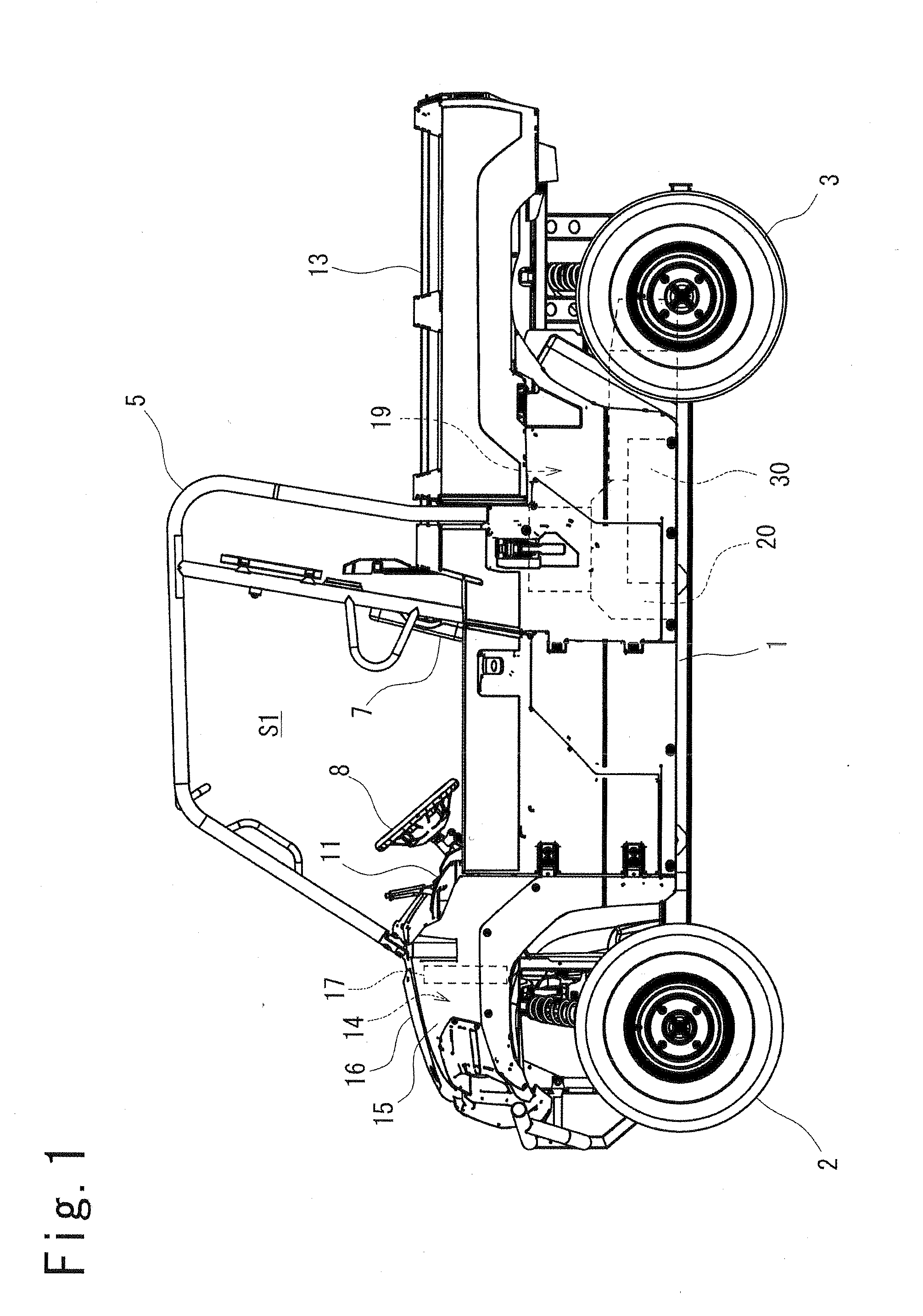
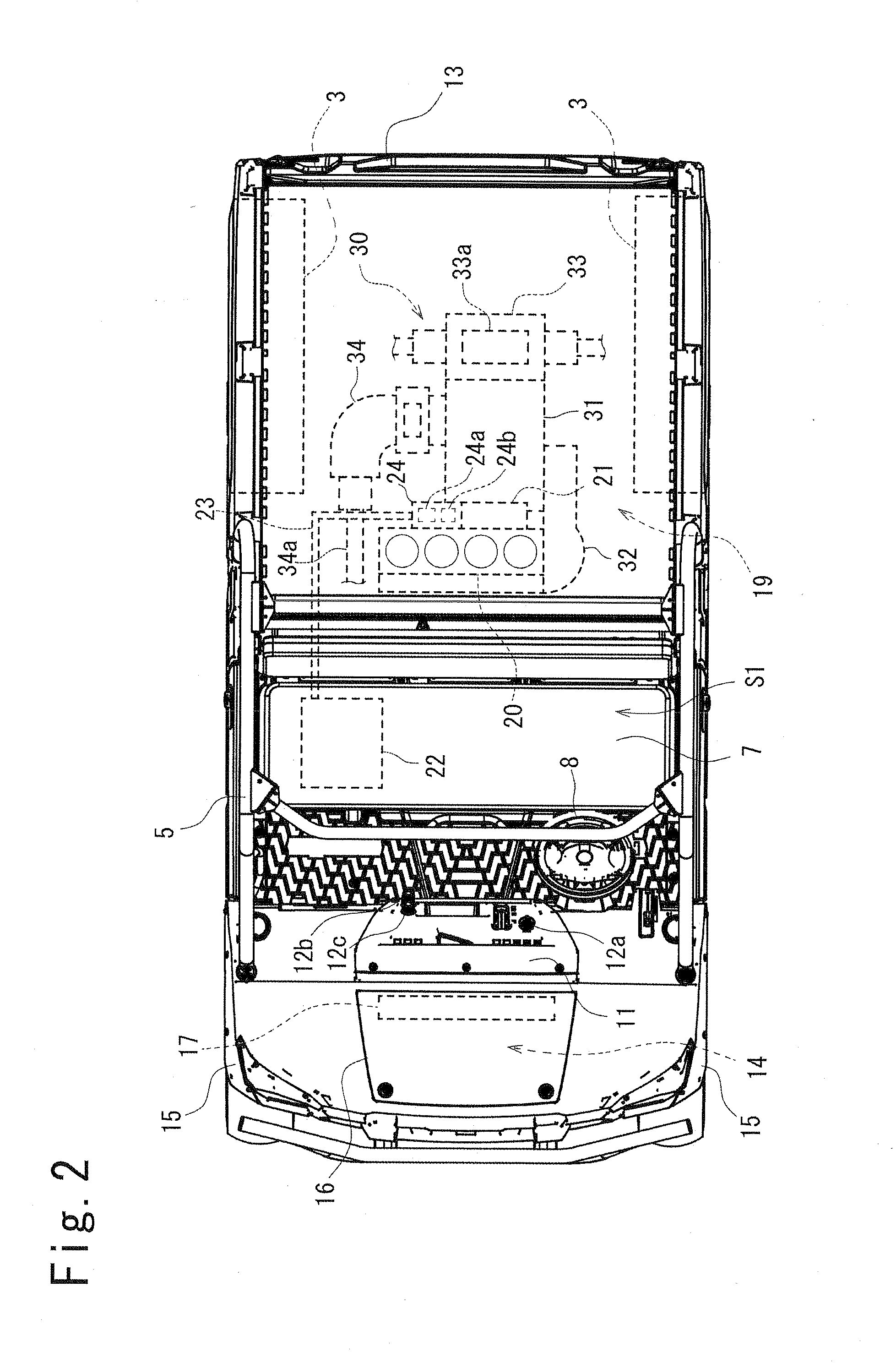
[0033]FIG. 1 is a left side view of the utility vehicle. The utility vehicle includes a chassis frame 1, right and left front wheels 2 provided at the front end of the chassis frame 1, and right and left rear wheels 3 provided at the rear end of the chassis frame 1. A riding space S1 is provided between the front wheels 2 and the rear wheels 3 in the anteroposterior direction, and is surrounded with a R.O.P.S. 5. The riding space S1 accommodates a front bench seat 7 and has a dashboard 11 at the front end. The R.O.P.S. is an abbreviation for a rollover protective structure.

[0034]Right and left front fenders 15 and a hood 16 are provided ahead of the dashboard 11. A dump truck type carrier 13 is provided behind the riding space S1.

[0035]An engine room 19 is provided below the carrier 13. The engine room 19 accommodates an engine 20 and a drive unit 30 configured to transmit driving power from the engine 20 deceler...

second embodiment

[0069](Second Embodiment)

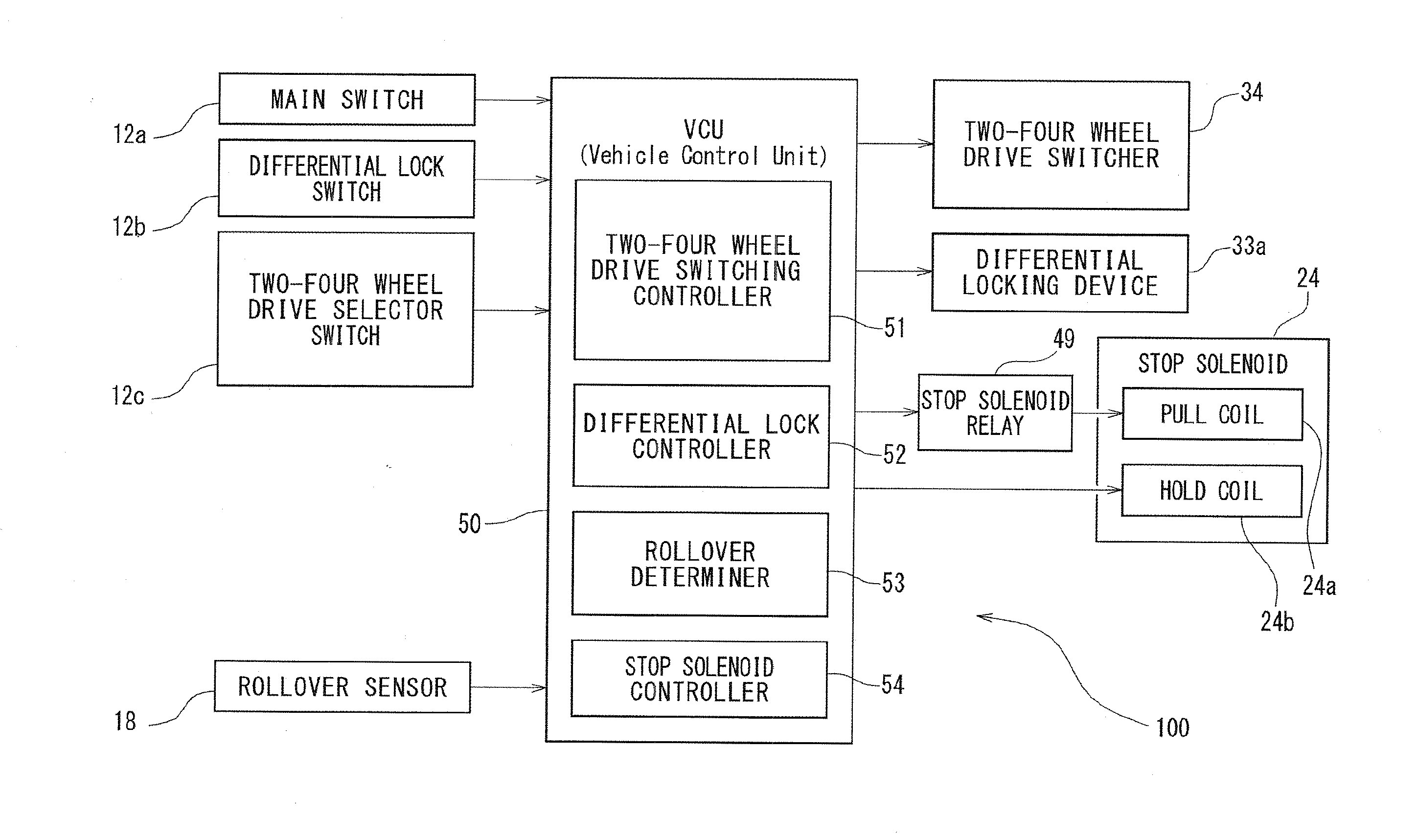
[0070]A utility vehicle according to the second embodiment will be described next with reference to FIGS. 8 and 9. The utility vehicle according to the second embodiment includes a control system 200 different from the control system 100 according to the first embodiment, while the remaining configurations are the same as those according to the first embodiment. The differences will be described below.

[0071][Configuration of Control System 200]

[0072]FIG. 8 is a block diagram showing a schematic configuration of the control system 200. The control system 200 includes, in addition to the configurations of the control system 100, a seat belt fastening detector 55. When the seat belt fastening detector 55 detects that a crew does not fasten a seat belt upon receipt a signal from a seat belt sensor 60, the control system 200 controls not to start the engine 20.

[0073]Specifically, the seat belt fastening detector 55 detects that a crew does not fasten the seat bel...


PUM


Abstract

A utility vehicle includes a diesel engine, a two-four wheel drive switcher provided on a driving power transmission path from the diesel engine and configured to switch transmission of driving power to driving wheels between a two-wheel drive mode and a four-wheel drive mode, and a vehicle control unit configured to control the two-four wheel drive switcher. The utility vehicle further includes a rollover sensor configured to detect rollover of the utility vehicle, and a fuel cutoff valve configured to cut off fuel supply to the diesel engine. The vehicle control unit determines whether or not the utility vehicle is being rolled over in accordance with detection by the rollover sensor and controls the fuel cutoff valve to cut off the fuel supply when the vehicle control unit determines that the utility vehicle is being rolled over.

Description

BACKGROUND OF THE INVENTION[0001]1. Field of the Invention[0002]The present invention relates to a utility vehicle, and particularly to a utility vehicle including a diesel engine.[0003]2. Description of the Related Art[0004]There has been conventionally known a utility vehicle including a diesel engine. Such a diesel engine mounted to a utility vehicle is mechanically supplied with fuel by a fuel injection pump that is driven and rotated directly by rotation of a crank shaft, is mechanically adjusted an amount of the supplied fuel by a centrifugal spark advancer, and is ignited by compressed self-ignition. In short, an engine of this type is not electronically controlled and does not include any engine control unit (ECU).[0005]An engine of this type is thus stopped by cutoff of fuel supply to the fuel injection pump, and includes a stop solenoid configured to cut off fuel supply to the fuel injection pump.[0006]The stop solenoid is provided on a fuel supply path from a fuel tank to...

Claims


Application Information

Patent Timeline
Patent Type & Authority Applications(United States)
IPC IPC(8): B60K28/14B60K17/34
CPCB60K28/14B60K2028/003B60K17/34
Inventor ITOO, SEIJITANAKA, SHINICHI
Owner KAWASAKI MOTORS LTD
Learn More