Evacuation method and vacuum processing apparatus

a vacuum processing and vacuum technology, applied in the direction of water supply installation, valve operating means/release devices, transportation and packaging, etc., can solve the problems of etching process after maintenance delay, moisture attached to wall surfaces and surfaces of component parts that are exposed to the atmosphere during maintenance, and difficulty in reducing a period of time of evacuation

Active Publication Date: 2016-06-30
TOKYO ELECTRON LTD
View PDF8 Cites 9 Cited by
  • Summary
  • Abstract
  • Description
  • Claims
  • Application Information

AI Technical Summary

Benefits of technology

[0009]Accordingly, to solve the above discussed problems, embodiments of the present invention aim to provide an evacuation method and a vacuum processing apparatus that reduce a pressure in a vacuum processing chamber to a predetermined pressure while preventing moisture inside the vacuum chamber from freezing.

Problems solved by technology

However, when performing the seasoning, a start of the etching process after the maintenance is delayed.
However, in the evacuation method of Japanese Laid-Open Patent Application Publication No. 2002-249876, when the pressure inside the vacuum chamber is reduced, moisture having attached to wall surfaces and surfaces of component parts that are exposed to the atmosphere during the maintenance, starts evaporating.
Frozen moisture continues to evaporate for a long time and traps moisture not yet frozen in small recesses in the wall surfaces and the like, thereby making it difficult to reduce a period of time of the evacuation.
Moreover, the frozen moisture may cause a failure such as generation of particles, abnormal discharge, and corrosion of component parts.

Method used


Image

  • Evacuation method and vacuum processing apparatus
  • Evacuation method and vacuum processing apparatus
  • Evacuation method and vacuum processing apparatus

Examples


Embodiment Construction

[0019]A description is given below of embodiments of the present invention, with reference to accompanying drawings. Note that elements having substantially the same functions or features may be given the same reference numerals and overlapping descriptions thereof may be omitted.

[0020][Overall Configuration of Vacuum Processing Apparatus]

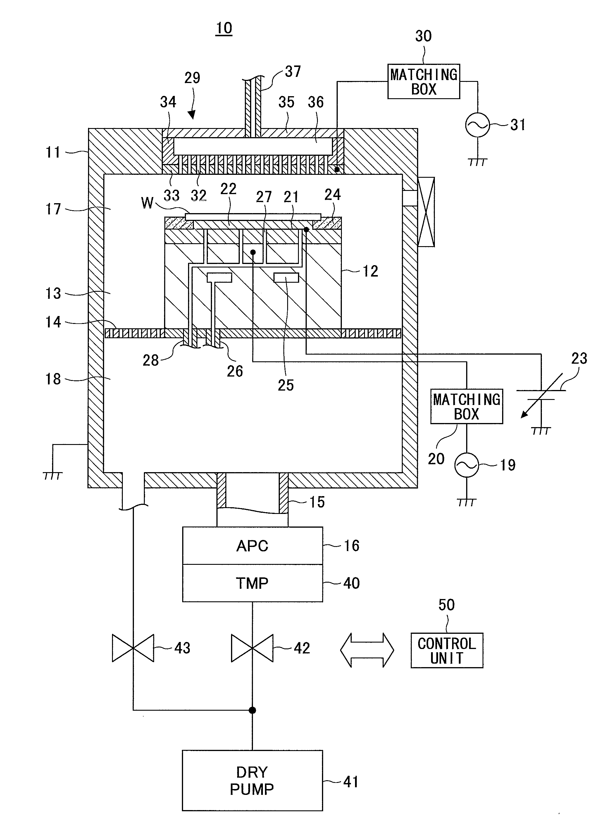
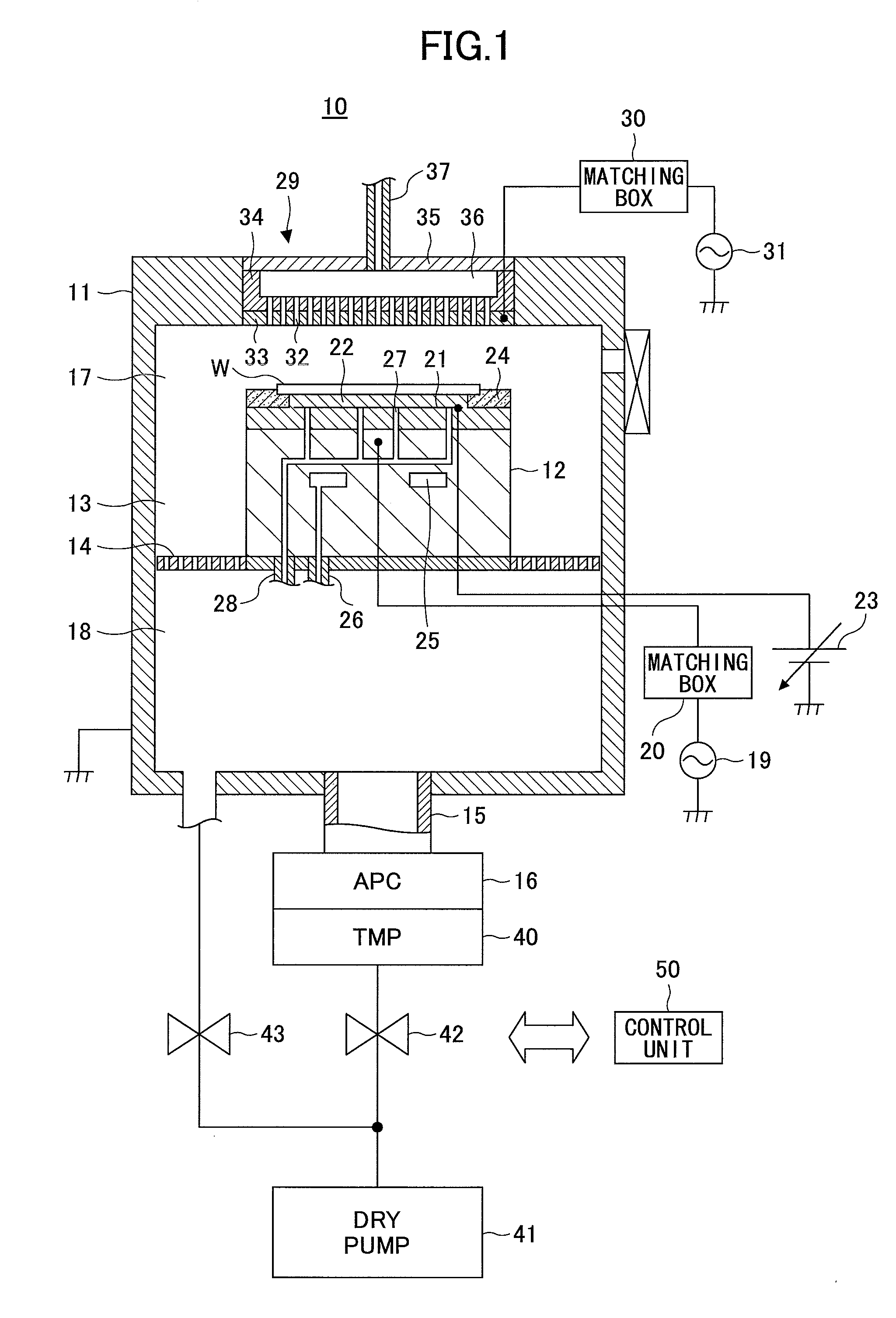
[0021]To begin with, a description is given below of an example of an overall configuration of a vacuum processing apparatus 10 according to an embodiment of the present invention with reference to FIG. 1. In the embodiment, the vacuum processing apparatus 10 is an apparatus to generate plasma in a vacuum processing chamber 11 and perform a plasma process such as an etching process on a semiconductor wafer (which is hereinafter also referred to as a “wafer W”) by an action of plasma. The vacuum processing apparatus 10 is made of aluminum and the like, and includes a cylindrical vacuum processing chamber 11 that can seal the inside thereof. The vacu...


PUM


Abstract

An evacuation method used for a vacuum processing apparatus including a vacuum processing chamber is provided. The vacuum processing chamber is evacuated by an exhaust device for a first predetermined period of time by opening a valve connecting the exhaust device with the vacuum processing chamber. A pressure in the vacuum processing chamber is urged to increase by closing the valve and leaving the valve closed for a second predetermined period of time after evacuating the vacuum processing chamber. Evacuating the vacuum processing chamber and urging the pressure in the vacuum processing chamber to increase are performed so as to reduce the pressure in the vacuum processing chamber to a pressure between 6.7 Pa and 13.3×10² Pa (between 5 Torr and 10 Torr) without freezing moisture in the vacuum processing chamber.

Description

CROSS-REFERENCE TO RELATED APPLICATIONS[0001]This patent application is based upon and claims the benefit of priority of Japanese Patent Application No. 2014-263378, filed on Dec. 25, 2014, the entire contents of which are incorporated herein by reference.BACKGROUND OF THE INVENTION[0002]1. Field of the Invention[0003]The present invention relates to an evacuation method and a vacuum processing apparatus.[0004]2. Description of the Related Art[0005]In vacuum processing apparatuses, a CD (Critical Dimension) control is performed to control a shift amount of a post-etching pattern dimension relative to a pre-etching mask dimension. However, in an etching process after maintenance for cleaning a vacuum chamber, a CD shift occurs in which a CD value deviates from a setting value. To solve this, it is proposed to perform the etching process after stabilizing an atmosphere in the vacuum chamber by seasoning the inside of the vacuum chamber after the cleaning, thereby preventing the CD shi...

Claims


Application Information

Patent Timeline
Patent Type & Authority Applications(United States)
IPC IPC(8): H01L21/67
CPCH01L21/67069H01L21/67017H01J37/32834Y10T137/0379H01J37/32449Y10T137/86027Y10T137/86002Y10T137/86083A61L2/14A61L2/24
Inventor HAGA, HIROFUMINAKAO, NOBUTAKAYAKUSHIJI, HIDEAKI
Owner TOKYO ELECTRON LTD
Why Eureka
Try Eureka