Storage apparatus and storage control method

a storage apparatus and control method technology, applied in the direction of storage adressing/allocation/relocation, instruments, input/output to record carriers, etc., can solve the problems of reducing the capacity of data, and reducing the number of times of data write. , to achieve the effect of reducing the number of blocks and reducing the number of deletions

Active Publication Date: 2016-07-07
HITACHI LTD
View PDF5 Cites 22 Cited by
  • Summary
  • Abstract
  • Description
  • Claims
  • Application Information

AI Technical Summary

Benefits of technology

[0021]A logical storage area having a larger capacity than physical capacities of semiconductor storage media is provided in a storage controller. Accordingly, the storage controller can store a larger capacity of data than the physical capacity of the semiconductor storage device, to the semiconductor storage device.

Problems solved by technology

However, the SSD has a disadvantage of shorter life than the HDD because the number of times of data write has an upper limit.
However, the number of times of the block deletion for each block (hereinafter, the number of times of deletion) has limitations in terms of a physical restriction of the flash memory.
If the number of times of deletion of the block exceeds the limitations, the data cannot be stored in the block.
In such a storage apparatus, even if the deterioration of only a specific block is suppressed in each SSD, loads among the SSD become unbalanced, and only a specific SSD may be overloaded.

Method used


Image

  • Storage apparatus and storage control method
  • Storage apparatus and storage control method
  • Storage apparatus and storage control method

Examples


first example

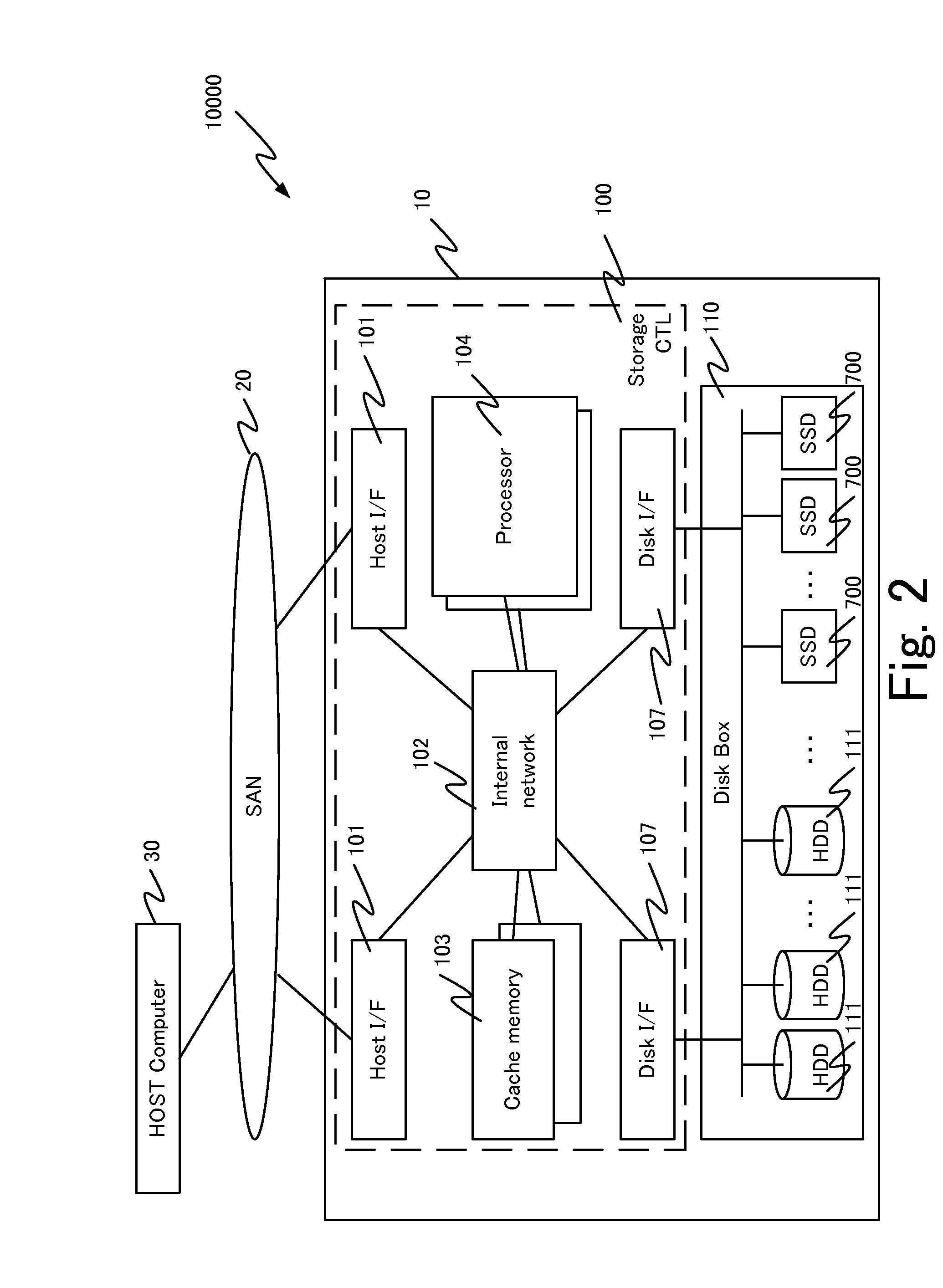
[0081]FIG. 2 is a diagram illustrating a configuration example of a storage system 10000 including a storage apparatus 10 according to a first example.

[0082]The storage system 10000 includes the storage apparatus 10 and a host computer 30. The host computer 30 is an example of an upper apparatus that uses the storage apparatus 10. The host computer 30 is an application server, for example. The host computer 30 and the storage apparatus 10 are communicatively coupled to each other through a storage area network (SAN) 20, for example. As the SAN 20, a fiber channel, a small computer system interface (SCSI), an internet small computer system interface (iSCSI), a universal serial bus (USB), an IEEE1394 bus, a serial attached SCSI (SAS), or the like can be used. Further, another type of communication network (for example, a local area network (LAN)) may be employed in place of the SAN 20. Note that, in the example of FIG. 2, the storage system 10000 includes one host computer 30 and one ...

second example

[0252]Next, a second example will be described. In the second example, a different portion from the first example will be mainly described.

[0253]While, in the first example, the compression ratio has been acquired as the average value of an SSD unit, in the second example, a compression ratio is acquired in units of entry. To be specific, an SSD controller 710 provides a data compression ratio of an entry unit to a response command to be transmitted to a storage controller 100 at the time of completion of WR. By reference to the data compression ratio included in the response command, the storage controller 100 can manage the compression ratio for each entry.

[0254]Accordingly, expectation accuracy of an FM WR expected amount of each entry can be enhanced, compared with the first example, and as a result, execution accuracy of life leveling processing can be improved.

[0255]FIG. 30 is a diagram illustrating a configuration example of a statistical information management table 13600 ac...

third example

[0268]Next, a third example will be described. Note that only different points from the first and second examples will be described in the third example.

[0269]In the third example, write amplification (WA) is added to information for expectation of an FM WR amount, in addition to the compression ratio.

[0270]Typically, processing unique to an SSD such as WL or reclamation occurs inside an SSD 700. Therefore, a data amount actually written in a flash memory is larger than a data amount actually acquired by the SSD 700 from a storage controller 100. A ratio of the data amount actually written in a flash memory to the received data amount is called WA. An increase in a WR data amount due to the processing inside the SSD also depends on an access pattern, a size of WR data, and the like.

[0271]When the WR data amount is increased due to the unique processing inside the SSD 700, the number of times of deletion is increased. Therefore, in the third example, the storage controller 100 additi...


PUM


Abstract

A storage apparatus includes a semiconductor storage device, and a storage controller coupled to the semiconductor storage device, and which stores data to a logical storage area provided by the semiconductor storage device. The semiconductor storage device includes one or more non-volatile semiconductor storage media, and a medium controller coupled to the semiconductor storage media. The medium controller compresses data stored in the logical storage area, and stores the compressed data in the semiconductor storage medium. The size of a logical address space of the logical storage area is larger than a total of the sizes of physical address spaces of the semiconductor storage media.

Description

TECHNICAL FIELD[0001]The present invention relates to storage control of a storage apparatus including a plurality of non-volatile semiconductor storage devices.BACKGROUND ART[0002]A storage apparatus typically includes a physical storage device that stores data and a controller that controls the physical storage device. The controller provides a computer (for example, a host computer) coupled with the storage apparatus with a data storage space (typically, a logical volume).[0003]The storage apparatus can speed up I / O processing and can exhibit high fault-tolerance against a breakdown of the physical storage device, by using a plurality of physical storage devices in redundant array of independent (or inexpensive) disks (RAID) configuration.[0004]The storage apparatus typically includes a hard disk drive (HDD) as the physical storage device. However, in recent years, as a new physical storage device replacing the HDD, a physical storage device including a flash memory (hereinafter,...

Claims


Application Information

Patent Timeline
Patent Type & Authority Applications(United States)
IPC IPC(8): G06F3/06G06F12/02
CPCG06F3/0616G06F12/0246G06F2212/7201G06F3/0655G06F3/0647G06F3/0688G06F3/0608G06F3/0638G06F3/0679G06F2212/7211
Inventor MATSUSHITA, TAKAKI
Owner HITACHI LTD
Why Eureka
Try Eureka