Permanent Magnet Synchronous Motor and Winding-Switching Motor Driving Device, and Refrigeration Air Conditioner and Electric Vehicle Using Same

a permanent magnet synchronous motor and driving device technology, applied in the direction of motor/generator/converter stopper, dynamo-electric converter control, lighting and heating apparatus, etc., can solve the problems of increasing the loss of booster circuit, reducing the efficiency of high-speed rotation range, and increasing the circuit scal

Active Publication Date: 2016-07-14
HITACHI LTD
View PDF1 Cites 43 Cited by
  • Summary
  • Abstract
  • Description
  • Claims
  • Application Information

AI Technical Summary

Benefits of technology

[0023]A permanent magnet synchronous motor of the present invention is a permanent magnet synchronous motor including at least two series-connected windings for each phase, and configured to be driven by selecting the windings using a multi-inverter driving device configured to switch between en inverter for low-speed drive and an inverter for high-speed drive. The permanent magnet synchronous motor of the present invention is characterized in that a ratio of an induced voltage constant of at least one group of windings constituting the windings for the high-speed drive and a d-axis inductance is larger than a ratio of an induced voltage constant of all the series-connected windings to the d-axis inductance.

Problems solved by technology

In the motor with low speed design, however, the drive range may be narrowed due to an increase in an induced voltage generated at a high-speed rotation range, and the efficiency at the high-speed rotation range may decrease significantly.
This method, however, requires addition of a circuit for boosting a DC voltage, and has problems of an increase in the circuit scale, and an increase in the loss of the booster circuit or the like.
For this reason, this method is difficult to apply no apparatuses which need to be driven continuously, such as main engines of electric automobiles.
However, this method has a problem that a loss in the semiconductor switches always occurs.
The techniques disclosed in Patent Documents 3 and 4 require the two inverter main circuits for driving the motor to be driven concurrently, which leads to a problem that a loss in the inverter main circuits is doubled to reduce the circuit efficiency.

Method used


Image

  • Permanent Magnet Synchronous Motor and Winding-Switching Motor Driving Device, and Refrigeration Air Conditioner and Electric Vehicle Using Same
  • Permanent Magnet Synchronous Motor and Winding-Switching Motor Driving Device, and Refrigeration Air Conditioner and Electric Vehicle Using Same
  • Permanent Magnet Synchronous Motor and Winding-Switching Motor Driving Device, and Refrigeration Air Conditioner and Electric Vehicle Using Same

Examples


first embodiment

Synchronous Motor

[0055]Descriptions will be hereinbelow provided for a permanent magnet synchronous motor of a first embodiment of the present invention.

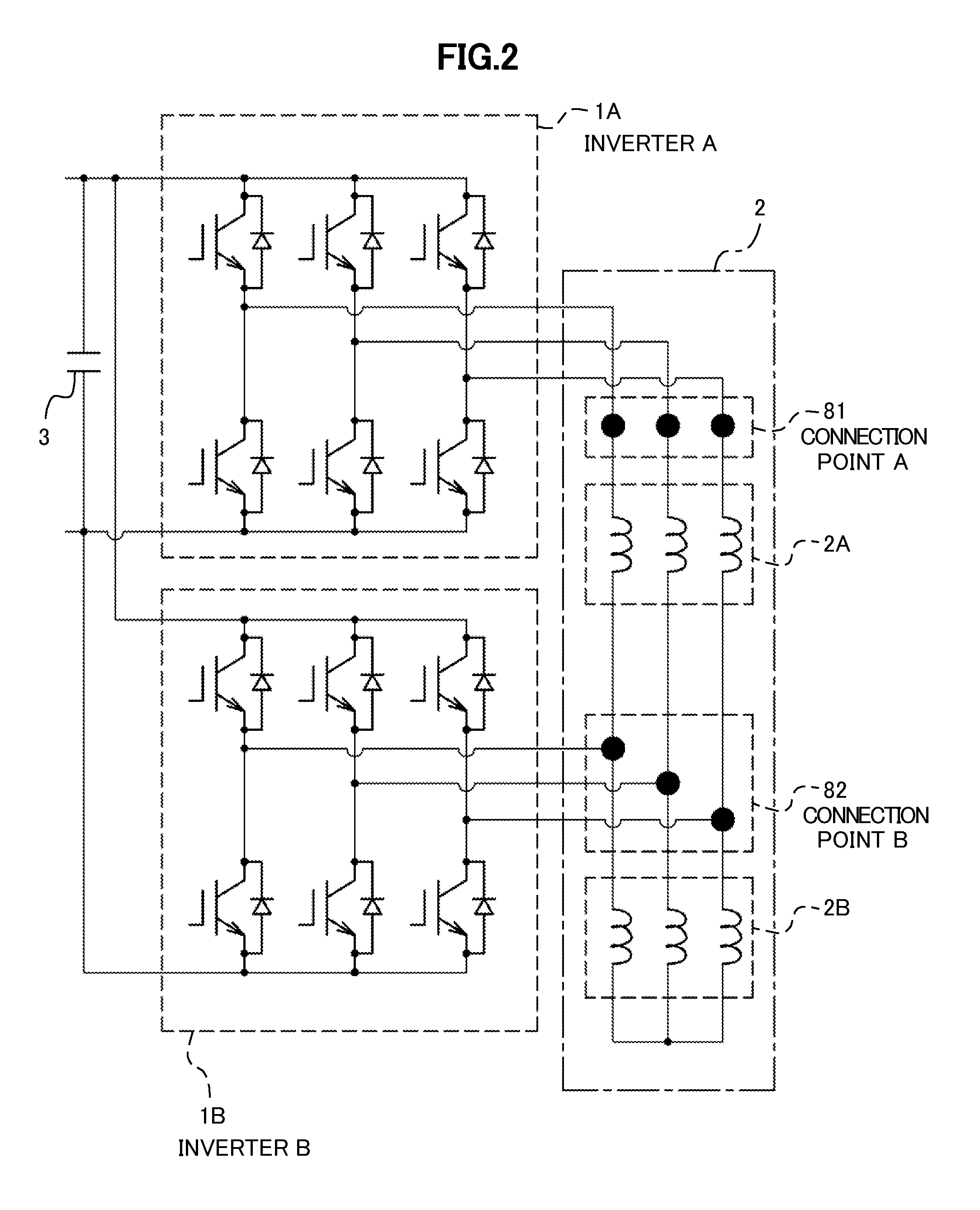
[0056]It should be noted that because the permanent magnet synchronous motor of the first embodiment of the present invention is closely connected with a driving method, descriptions of a winding-switching motor driving device will be added into the descriptions of the permanent magnet synchronous motor as needed.

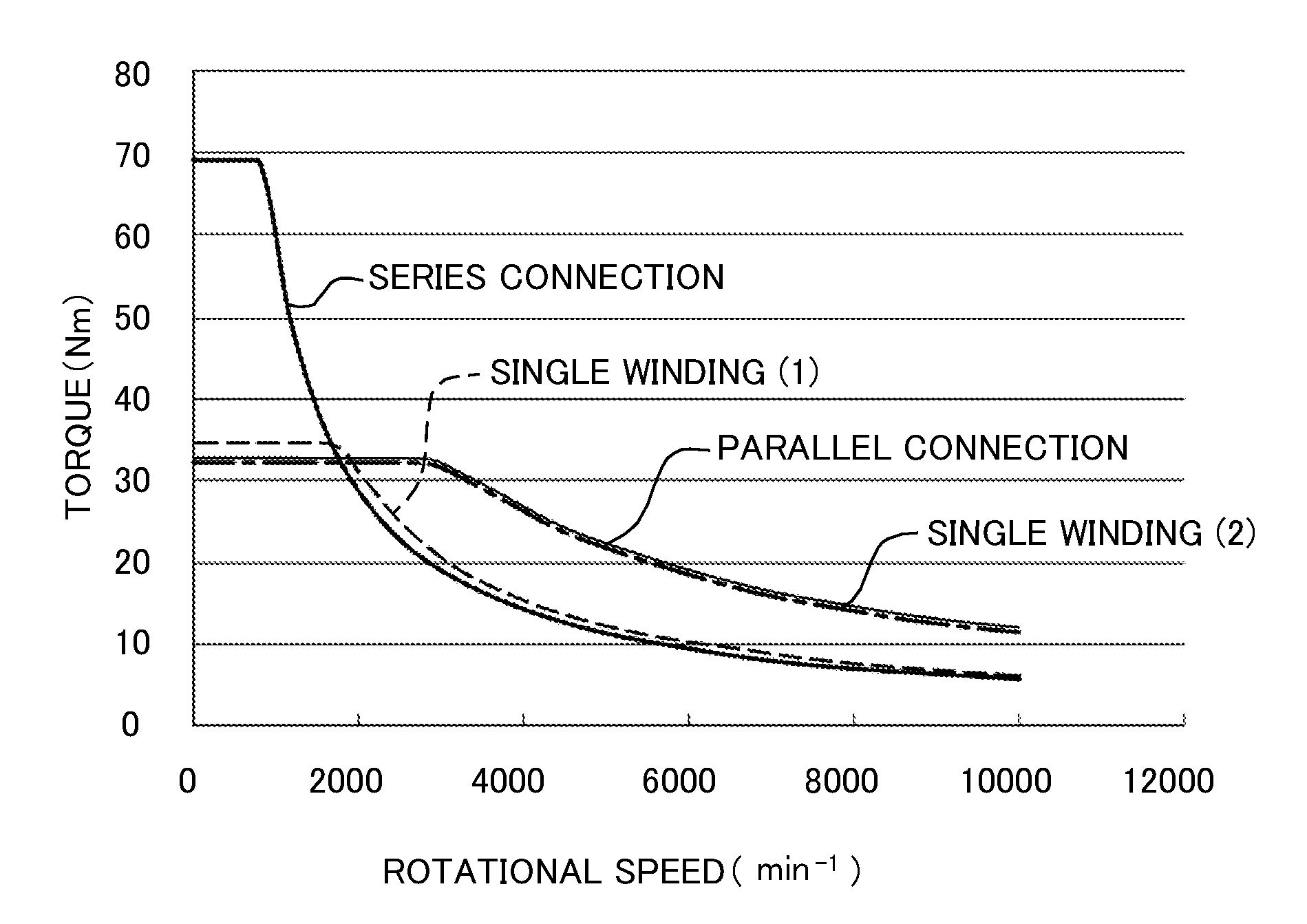
[0057]In addition, as a main component, the permanent magnet synchronous motor will be described together with contents under subtitles “Schematic Configuration of Permanent Magnet Synchronous Motor,”“Relationship between Permanent Magnet Synchronous Motor and Winding-switching Motor Driving Device,”“Detailed Configuration of Permanent Magnet Synchronous Motor,”“Comparison of Characteristics,” and “Effects of First Embodiment” in this order.

[0058]Furthermore, descriptions of the contents under the subtitle “Comparison of Ch...

second embodiment

Synchronous Motors

[0183]Next, as a second embodiment, another mode of the motor winding structure of the present invention will be described with reference to FIGS. 9 to 11.

[0184]FIG. 9 is a diagram showing a winding structure of a permanent magnet synchronous motor of the second embodiment of the present invention.

[0185]FIG. 10 includes diagrams each showing how windings are placed in each stator of an axial permanent magnet synchronous motor of the second embodiment of the present invention.

[0186]FIG. 11 is a diagram showing how windings are placed in a stator of a radial permanent magnet synchronous motor of the second embodiment of the present invention.

[Winding Configuration]

[0187]In FIG. 9, the winding configuration includes the winding 2A and the winding 2B, as in the case of the first embodiment. Furthermore, the winding 2A has a series connection configuration, and the winding 2B has a parallel connection configuration.

[0188]To put it concretely, the winding 2A includes two...

third embodiment

Synchronous Motor

[0202]Next, as a third embodiment, an example of a motor structure which is applied to an electric car driving motor (an in-wheel motor in particular) will be described referring to FIG. 12.

[0203]FIG. 12 is a diagram showing an example of the structure in which a permanent magnet synchronous motor of the third embodiment of the present invention is applied to the in-wheel motor.

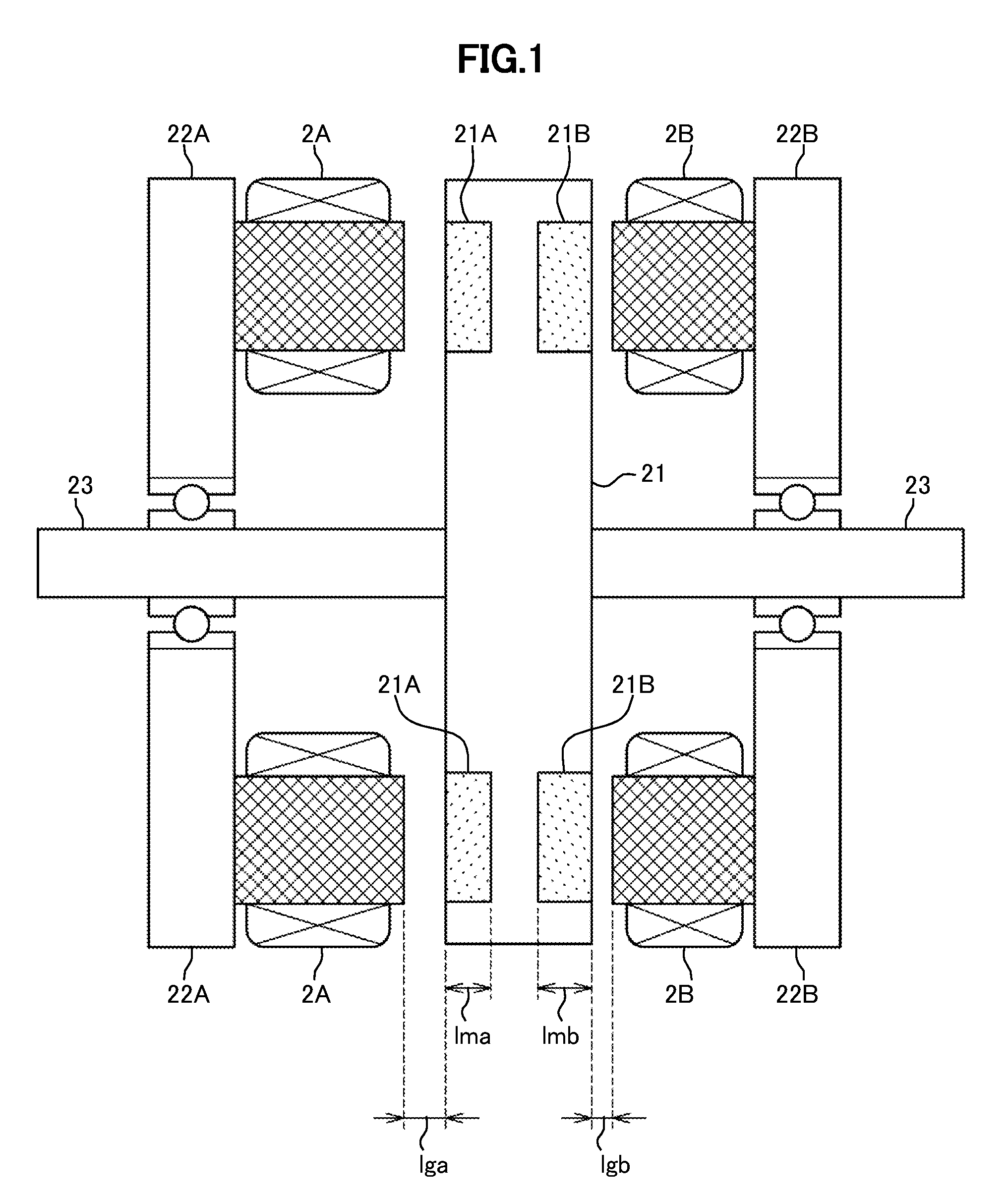
[0204]What is shown in FIG. 12 is the structure suitable for the in-wheel motor which is obtained by changing the structure shown in FIG. 1.

[0205]It should be noted that the reference signs in FIG. 12 correspond to parts and elements denoted by the same reference signs in FIG. 1. The parts and elements denoted by the same reference signs as those in FIG. 1 have the same characteristics.

[0206]No other major changes are made. Duplicate descriptions will be omitted.


PUM


Abstract

A permanent magnet synchronous motor includes at least two series-connected windings for each phase, and is configured to be driven by selecting the windings using a multi-inverter driving device configured to switch between an inverter for low-speed drive and an inverter for high-speed drive. A ratio of an induced voltage constant of at least one group of windings constituting the windings for the high-speed drive and a d-axis inductance is larger than a ratio of an induced voltage constant of all the series-connected windings to the d-axis inductance.

Description

BACKGROUND OF THE INVENTION[0001]1. Field of the Invention[0002]The present invention relates to a permanent magnet synchronous motor and a winding-switching motor driving device, and a refrigeration air conditioner and an electric vehicle using the same.[0003]2. Description of the Related Art[0004]The permanent magnet synchronous motor (also simply referred to as “motor” below as needed) is characterized by having higher efficiency than the induction motor, and the application range of the motors has been widened to include not only the field of home appliances, but also the fields of industrial apparatuses and electronic motors.[0005]In addition, the motors, appliances, and apparatuses are required to achieve higher efficiency at a low-speed rotation range (light load) in order to meet the movement toward prevention of global warming and energy saving, and are also required to have ability to drive at a high speed rotation range (high load) in order to improve the sense of use (co...

Claims


Application Information

Patent Timeline
Patent Type & Authority Applications(United States)
IPC IPC(8): H02P25/22B60L15/02F25B31/02H02K3/28
CPCH02P25/22F25B31/026B60L15/02H02K3/28B60L7/14B60L7/16B60L15/025B60L2210/40B60L2220/14B60L2220/56B60L2240/421H02P27/08Y02T10/64Y02T10/72
Inventor NOTOHARA, YASUOMARUYAMA, ERIHATSUSE, WATARUTAKAHATA, RYOUICHI
Owner HITACHI LTD
Why Eureka
Try Eureka