Inkjet chip and contro circuit of printing module of rapid prototyping apparatus

a printing module and control circuit technology, applied in applications, manufacturing tools, instruments, etc., can solve the problems of increasing the cost of carrying seats and ink cartridges, increasing the size of the entire printing module b>1/b>, and achieving high efficiency operation and facilitate heating circuits

Active Publication Date: 2016-07-21
MICROJET TECH
View PDF3 Cites 5 Cited by
  • Summary
  • Abstract
  • Description
  • Claims
  • Application Information

AI Technical Summary

Benefits of technology

[0008]An object of the present invention provides an inkjet chip of a printing module of a rapid prototyping apparatus. The inkjet chip includes a plurality of liquid ejectors arranged in plural rows and disposed in staggered arrangement, so as to facilitate the heating circuits of the liquid ejectors to be performed in high efficient operation.

Problems solved by technology

Consequently, the entire size of the printing module 1 will be increased, and the cost of the carrying seat and the ink cartridge will be increased.

Method used


Image

  • Inkjet chip and contro circuit of printing module of rapid prototyping apparatus
  • Inkjet chip and contro circuit of printing module of rapid prototyping apparatus
  • Inkjet chip and contro circuit of printing module of rapid prototyping apparatus

Examples


first embodiment

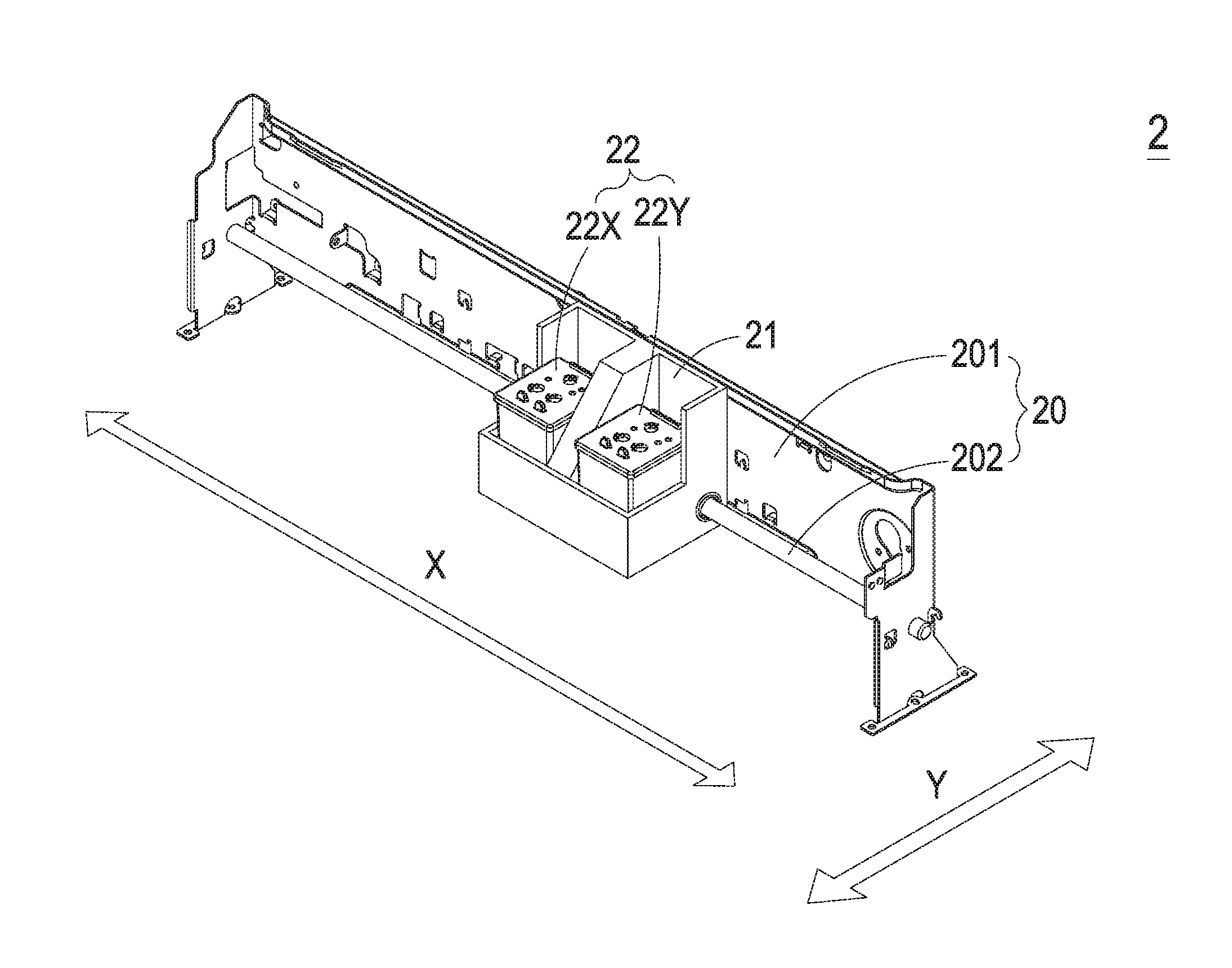
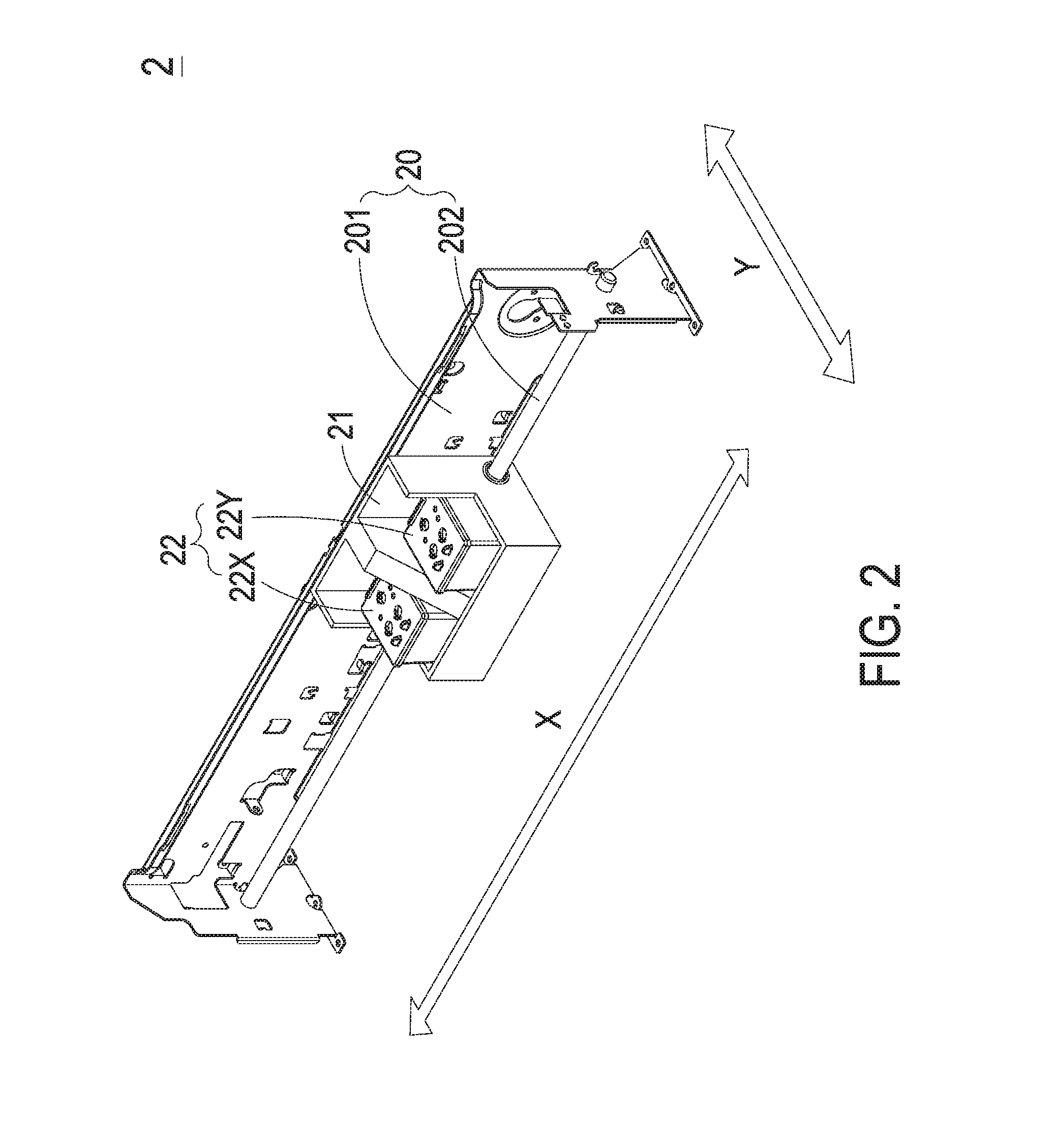
[0032]FIG. 2 is a schematic view illustrating a printing module of a rapid prototyping apparatus according to the present invention. As shown in FIG. 2, the printing module 2 is used in a rapid prototyping apparatus (not shown), and includes a printing platform 20, a carrying seat 21 and a plurality of modular ink cartridges 22 (hereinafter also referred to as ink cartridge). The printing platform 20 has a frame 201 and a driving shaft 202, and the driving shaft 202 is installed on the frame 201. The carrying seat 21 is penetrated and disposed on the driving shaft 202. In the embodiment, the plural ink cartridges 22 are two identical modular ink cartridges 22X, 22Y correspondingly disposed on the carrying seat 21. Consequently, the carrying seat 21 and the two ink cartridges 22X, 22Y thereon can be moved relative to the transmission shaft 202 of the inkjet printing platform 20 along a single axis (i.e. the X-direction) in a reciprocating motion. The print liquids are contained in pl...

second embodiment

[0065]Please refer to FIGS. 9A, 9B, 9C and 9D. FIG. 9A is a schematic bottom view illustrating the ink cartridge according to the present invention. FIG. 9B is a schematic top and cross-sectional view illustrating the ink cartridge of FIG. 9A. FIG. 9C is a cross-sectional view illustrating the ink cartridge of FIG. 9A and taken along line D-D′. FIG. 9D is a cross-sectional view illustrating the ink cartridge of FIG. 9A and taken along line E-E′. As shown in FIGS. 9A and 9B, the structure of the ink cartridge 42 is similar to the above embodiment. The case body 421 of the ink cartridge 42 has three ink chambers 425, 426, 427 and the ink cartridge 42 includes an inkjet chip 423 disposed on the bottom of the case body 421. In the embodiment, the number of the liquid supply slots 424 included in the inkjet chip 423 is different from that of the above embodiment. In the embodiment, preferably but not exclusively, the number of the liquid supply slots 424 is 3.

[0066]As shown in FIGS. 9B a...


PUM

PropertyMeasurementUnit
distanceaaaaaaaaaa
width Wd2aaaaaaaaaa
width Wd2aaaaaaaaaa

Abstract

An inkjet chip of printing module of a rapid prototyping apparatus and a control circuit thereof are disclosed. The inkjet chip has a length and a width to define a total area including an unwiring area and a wiring area. The unwiring area has at least three liquid supply slots in parallel with each other and respectively connected to one of the ink chambers of the modular ink cartridge. The wiring area has a control circuit. The control circuit includes a plurality of liquid ejectors. Each liquid ejector has a heating resistor, a driving transistor, and a nozzle. The control circuit is connected to receive a power signal, a printing data signal, a preheating data signal, a preheating control signal, a reverse preheating control signal, a heating control signal, and a reverse heating control signal and connected with the common connection node for controlling the liquid ejector.

Description

FIELD OF THE INVENTION[0001]The present invention relates to an inkjet chip and control circuit thereof, and more particularly to an inkjet chip of a printing module of a rapid prototyping apparatus and a control circuit thereof.BACKGROUND OF THE INVENTION[0002]As known, the rapid prototyping (RP) technology is developed from the concepts of forming a pyramid by stacking layers, and the main technical feature is to achieve fast formation. A complicated design can be transformed into a three-dimensional physical model automatically and fast without any cutting tools, molds and fixtures. Thus, the development cycle of new products and research and development cost are largely reduced to ensure the time to market for new products and the first-time-right ratio. Accordingly, a complete and convenient product design tool is provided between technicians and non-technicians (e.g. managers and users), and the product competitiveness and the quick reaction capability of enterprises in the ma...

Claims


Application Information

Patent Timeline
Patent Type & Authority Applications(United States)
IPC IPC(8): B29C67/00
CPCB29C67/0088B33Y30/00B33Y50/02B29C67/0059B41J2/14145B41J2/04528B41J2/04541B41J2/0458B41J2/1404B41J2/17513B41J2/1752B41J2/1753B41J2/17546B41J2/17553B41J29/02B29C64/112B29C64/393H01R9/2416H01R13/52G01R11/04
Inventor LIAO, WEN-HSIUNGHUANG, CHI-FENG
Owner MICROJET TECH
Why Eureka
Try Eureka