Adaptive optics system and optical device

a technology of adaptive optics and optical devices, applied in the field of adaptive optics systems and optical devices, can solve problems such as wave aberration, and achieve the effect of high accuracy

Active Publication Date: 2016-07-21
INTER UNIV RES INST NAT INST OF NATURAL SCI
View PDF3 Cites 34 Cited by
  • Summary
  • Abstract
  • Description
  • Claims
  • Application Information

AI Technical Summary

Benefits of technology

[0039]According to the present invention, the fluctuation correction surface and the fluctuation layer are imaging-conjugated with each other in the adaptive optics system, and it is thus possible

Problems solved by technology

When the observation target is a cell, however, there arises a problem that the cell surface or a spec

Method used


Image

  • Adaptive optics system and optical device
  • Adaptive optics system and optical device
  • Adaptive optics system and optical device

Examples


first embodiment

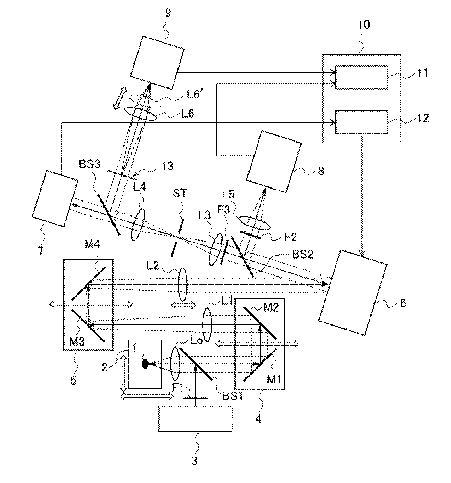
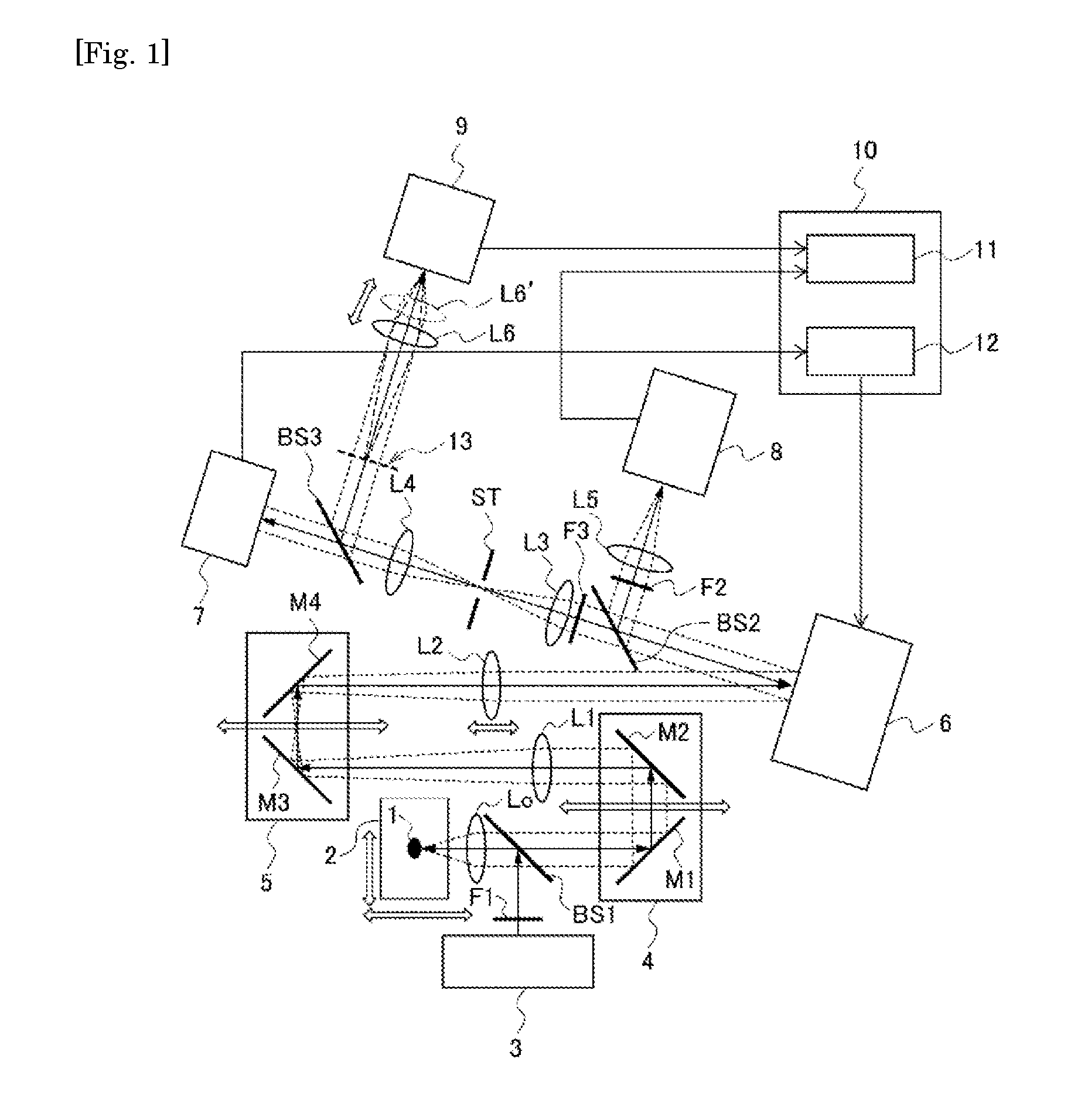
[0082]First, a microscopic device according to a first embodiment of the present invention will be described, taking a fluorescence microscope as an example. FIG. 1 is a schematic diagram illustrating a configuration of the microscopic device of the embodiment, and FIG. 2 is a schematic diagram illustrating a configuration example of a specimen 1.

[Entire Configuration]

[0083]The microscopic device of the embodiment includes an adaptive optics system so that the position of an imaging-conjugated surface relative to a fluctuation correction surface of the adaptive optics system is freely adjustable. Specifically, as shown in FIG. 1, the microscopic device of the embodiment includes a light source 3, a wavefront phase modulator 6, a wavefront sensor 7, an imaging camera 8, a pupil camera 9, a computer 10, and others.

[0084]In the microscopic device, an objective lens Lo, a beam splitter BS1, mirrors M1 and M2, a relay lens L1, mirrors M3 and M4, and a relay lens L2 are arranged in this o...

first modification example

of the First Embodiment

[0146]Next, a microscopic device according to a first modification example of the first embodiment of the present invention will be described. FIG. 8 is a diagram illustrating a configuration example of an adaptive optics system in a microscopic device as the modification example. FIG. 9 includes schematic diagrams illustrating operations of an imaging-conjugated position adjustment mechanism for fluctuation correction surface in the adaptive optics system. In FIG. 8, the same constituent elements as those of the microscopic device of the first embodiment described above are given the same reference signs as those of the first embodiment, and descriptions thereof will be omitted. FIG. 8 illustrates only the elements related to the position adjustment of the imaging-conjugated surface relative to the fluctuation correction surface in an equivalent manner, but does not illustrate the elements not directly related to the position adjustment.

[0147]The distance lc′...

second modification example

of the First Embodiment

[0154]Next, a microscopic device of a second modification example of the first embodiment in the present invention will be described. FIG. 10 is a diagram illustrating a configuration example of an adaptive optics system in a microscopic device of the modification example. In FIG. 10, the same constituent elements as those of the microscopic device of the first modification example of the first embodiment described above are given the same reference signs as those of the first modification example of the first embodiment, and descriptions thereof will be omitted. FIG. 10 illustrates only the elements related to the position adjustment of the imaging-conjugated surface relative to the fluctuation correction surface in an equivalent manner, but does not illustrate the elements not directly related to the position adjustment.

[0155]When the objective lens Lo is focused on the object target at infinity, as the position of the reference object becomes distant from t...


PUM


Abstract

The present invention is intended to provide an adaptive optics system and an optical device that allow correction of wavefront phase aberration with higher accuracy than before and have a wider correction range than the conventional ones, regardless of the distance between the observation target and the fluctuation layer, and the size of the observation target. An adaptive optics system includes: a wavefront phase modulator that makes aberration correction to incident light and emits the corrected light; and an imaging-conjugated position adjustment mechanism that adjusts freely within a specimen the position of a surface imaging-conjugated with a fluctuation correction surface formed by the wavefront phase modulator. The imaging-conjugated position adjustment mechanism adjusts the fluctuation correction surface to be imaging-conjugated with a fluctuation layer existing in the specimen.

Description

TECHNICAL FIELD[0001]The present invention relates to an adaptive optics system and an optical device including the adaptive optics system, more specifically, to a technique for correcting aberration resulting from an observation target.BACKGROUND[0002]Microscopic devices are generally used to observe biological specimens such as cells. When the observation target is a cell, however, there arises a problem that the cell surface or a specific subcellular organelle forms a fluctuation (distortion) generating layer to cause wave aberration. In addition, when the observation target is a biological tissue or organ, the tissue surface or a specific tissue layer forms a main distortion generating layer. Accordingly, various studies have been conventionally conducted for microscopic devices for use in observation of biological specimens to correct wave aberration resulting from the observation target and obtain high-quality microscopic images (refer to Patent Documents 1 to 4).[0003]For exa...

Claims


Application Information

Patent Timeline
IPC IPC(8): G02B27/00G02B21/36G02B21/18G02B21/00G01J9/00G02B17/00G02B21/02
CPCG02B27/0068G02B17/008G02B21/361G02B21/367G01J2009/002G02B21/0096G01J9/00G02B21/18G02B21/02G02B21/06G02B27/0025G02B21/002G01N21/6458G01N2021/1787A61B5/0059A61B5/0068A61B5/0071
Inventor HATTORI, MASAYUKITAMADA, YOSUKEMURATA, TAKASHIKAMEI, YASUHIROHASEBE, MITSUYASUHAYANO, YUTAKAOYA, SHIN
Owner INTER UNIV RES INST NAT INST OF NATURAL SCI
Why Eureka
Try Eureka