Graphene-based Plasmonic Nano-antenna for Terahertz Band Communication

a plasmonic nano-antenna and terahertz band technology, applied in the field of nano-scale antennas, can solve the problems of affecting the feasibility of nanonetworks, affecting the communication between nano-devices, and affecting the propagation of nano-devices,

Inactive Publication Date: 2016-07-28
GEORGIA TECH RES CORP
View PDF4 Cites 14 Cited by
  • Summary
  • Abstract
  • Description
  • Claims
  • Application Information

AI Technical Summary

Problems solved by technology

Currently, enabling the communication among nano-devices is still a mostly unsolved challenge.
The available transmission bandwidth increases with the antenna resonant frequency, but so does the propagation loss.
Due to the expectedly very limited power of nano-devices, the feasibility of nanonetworks would be compromised if this approach were followed.
In addition, it is not yet clear how a miniature transceiver could be engineered to operate at these v...

Method used


Image

  • Graphene-based Plasmonic Nano-antenna for Terahertz Band Communication
  • Graphene-based Plasmonic Nano-antenna for Terahertz Band Communication
  • Graphene-based Plasmonic Nano-antenna for Terahertz Band Communication

Examples


Embodiment Construction

[0020]A preferred embodiment of the invention is now described in detail. Referring to the drawings, like numbers indicate like parts throughout the views. Unless otherwise specifically indicated in the disclosure that follows, the drawings are not necessarily drawn to scale. As used in the description herein and throughout the claims, the following terms take the meanings explicitly associated herein, unless the context clearly dictates otherwise: the meaning of “a,”“an,” and “the” includes plural reference, the meaning of “in” includes “in” and “on.”

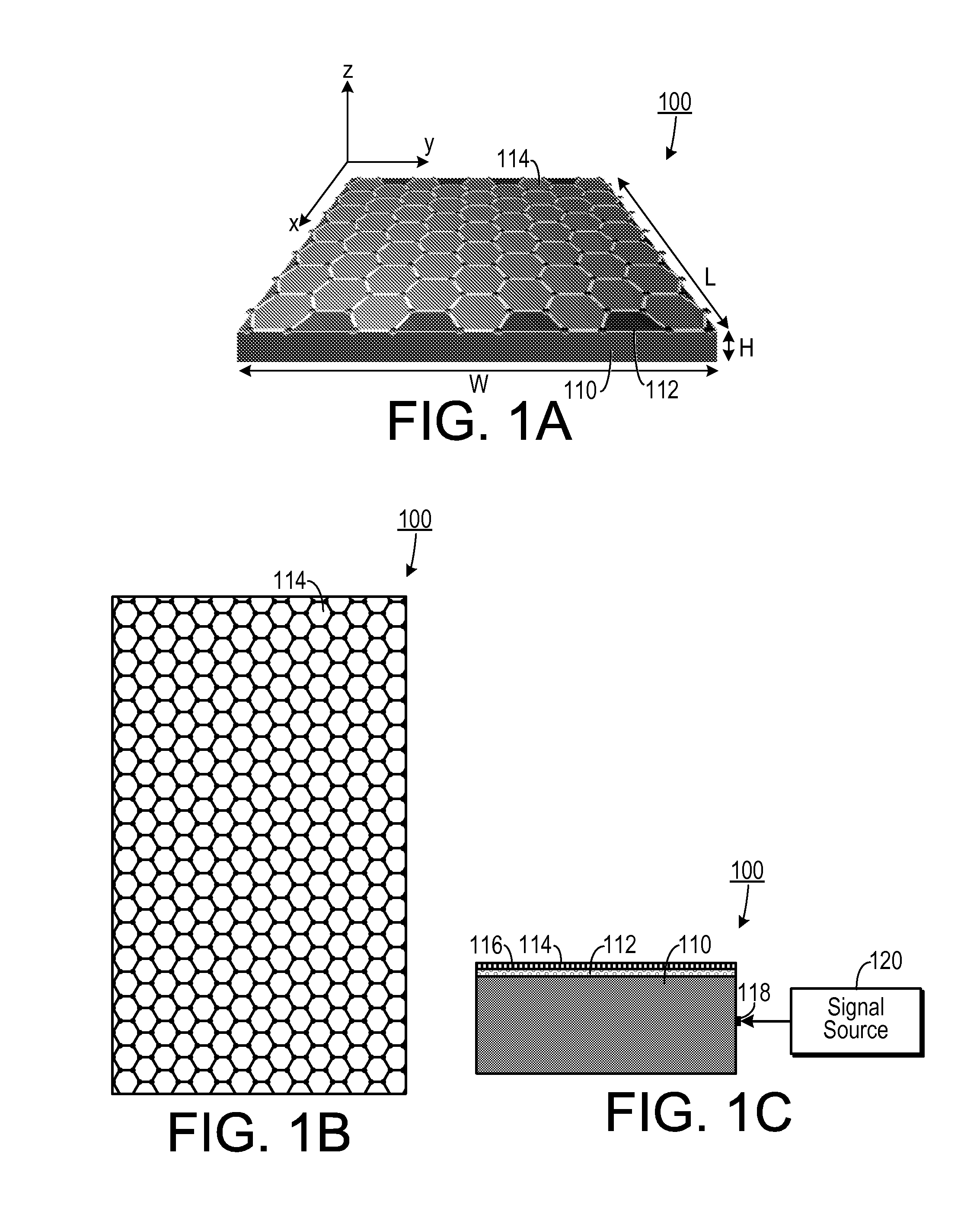
[0021]As shown in FIG. 11B, one embodiment of an antenna 100 includes an elongated conductive plane 110 that includes a material that is conductive to a signal with a frequency in a terahertz band, such as gold or platinum (or combinations thereof). An elongated dielectric layer 112 is disposed on the conductive plane 110. The dielectric layer 112 can include any material that acts as a dielectric with respect to signals in terahertz f...


PUM


Abstract

An antenna system includes an elongated conductive plane and an elongated dielectric layer that is disposed on the conductive plane. An elongated graphene nanoribbon is disposed along an axis and is coupled to the dielectric layer at a graphene/dielectric interface. A feeding mechanism is coupled to the conductive plane. The feeding mechanism is configured to accept a signal that excites surface plasmon polariton waves at the graphene/dielectric interface. In a method of making a surface plasmon polariton wave antenna, an elongated conductive plane is formed. An elongated dielectric layer is applied on a surface of the conductive plane. An elongated graphene nanoribbon is applied to the dielectric layer. A signal source is coupled to the elongated conductive plane.

Description

CROSS-REFERENCE TO RELATED APPLICATION(S)[0001]This application claims the benefit of U.S. Provisional Patent Application Ser. No. 61 / 812,872, filed Apr. 17, 2013, the entirety of which is hereby incorporated herein by reference.BACKGROUND OF THE INVENTION[0002]1. Field of the Invention[0003]The present invention relates to nano-scale antennas and, more specifically, to a plasmonic nano-scale antenna.[0004]2. Description of the Related Art[0005]An antenna converts an electrical signal into a transmission of radio waves and converts radio waves into an electrical signal. Most antennas operate at the macro scale and are used for communications between conventional radio-frequency transceivers.[0006]Nanotechnology is providing a new set of tools to the engineering community to design and eventually manufacture novel electronic components that may be no more than a few cubic nanometers in size and that will be able to perform specific functions, such as computing, data storing, sensing ...

Claims


Application Information

Patent Timeline
IPC IPC(8): H01Q9/42B82B3/00B82Y10/00
CPCH01Q9/42Y10S977/95B82B3/0038B82Y10/00H01Q1/38
Inventor AKYILDIZ, IAN F.JORNET, JOSEP MIQUEL
Owner GEORGIA TECH RES CORP
Why Eureka
Try Eureka