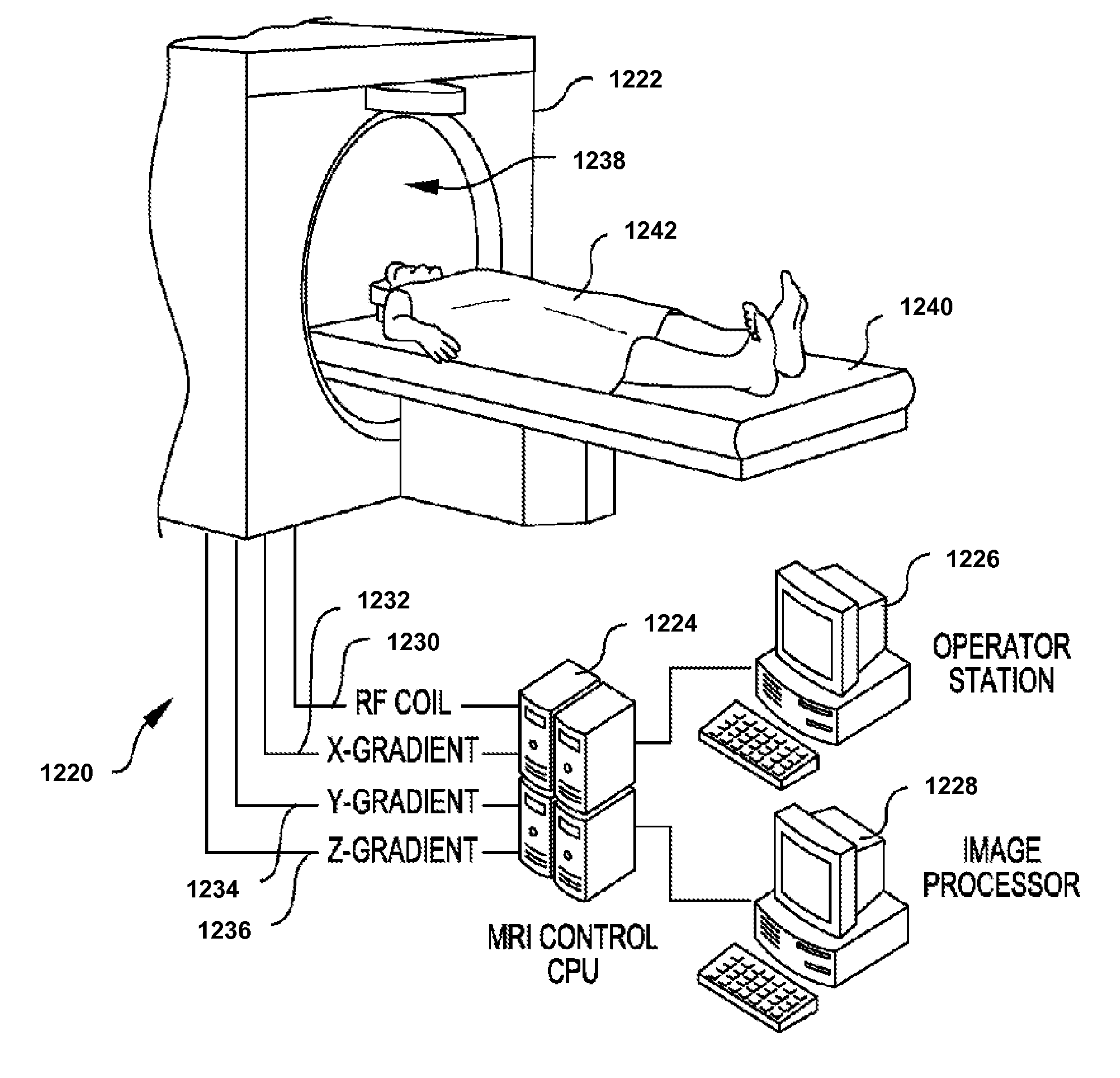
Method and system for analysis of volumetric data
a volumetric imaging and volumetric data technology, applied in the field of volumetric imaging data characterization and modeling, can solve problems such as significant technical challenges, and achieve the effect of eliminating topological errors and reducing computational tim
- Summary
- Abstract
- Description
- Claims
- Application Information
AI Technical Summary
Benefits of technology
Problems solved by technology
Method used
Image
Examples
example 1
Brain Morphology from MRI Data
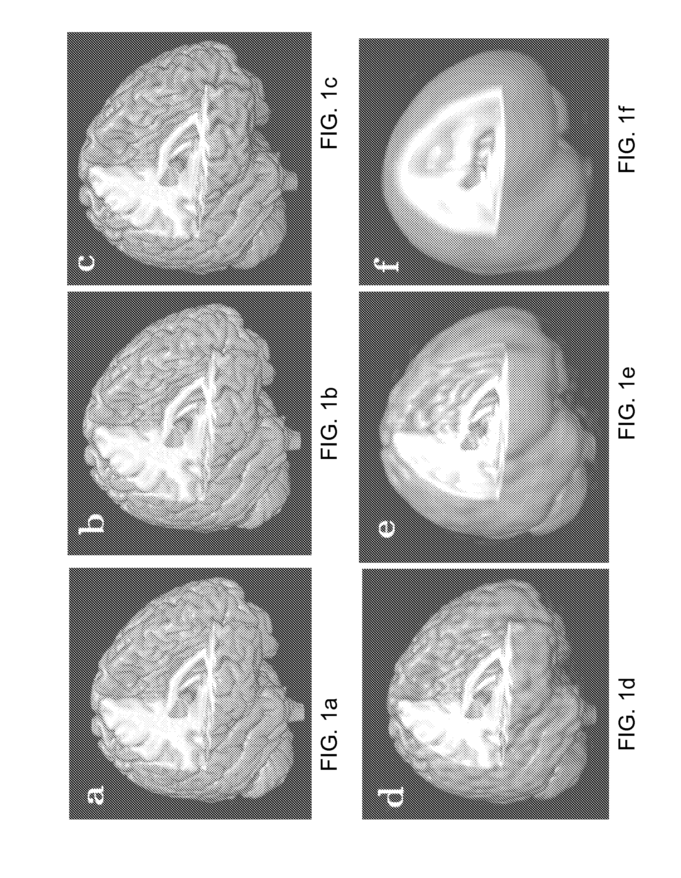
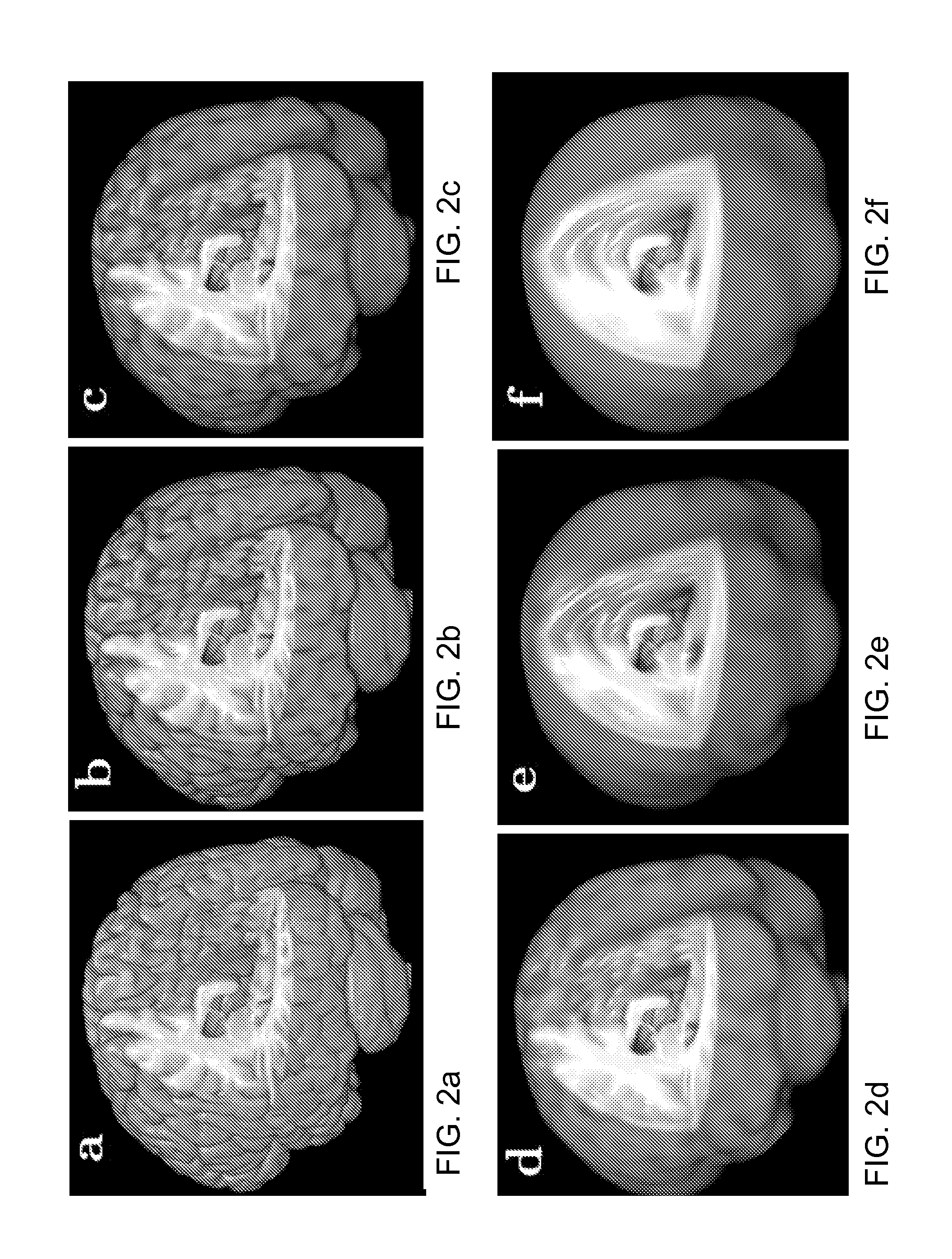
[0048]The SWD method was tested on high resolution MRI anatomical data of a normal human brain collected an a GE 3T MR750 Clinical Scanner using an inversion recovert T1-weighted 3D fast spoiled gradient recalled echo pulse sequence with parameters: flip angle a=12°, echo time TE=3 ms, repetition time TR=8 ms, matrix size=(RL, AP, IS)=(172×256×256), field of view FOV=(170×240×240) mm for a resolution of (1×0.938×0.938)mm. Characterization of this data as a function of SWD degrees Lmax and Nmax is shown in FIGS. 1a-1f for progressively lower degrees of SWD transform. The largest degree (Lmax=Nmax=300, shown in FIG. 1b) to exceed the physical dimensions of the original brain (FIG. 1a) confirms that a high degree SWD is capable of reconstructing all details of the original dataset and produce a visually indistinguishable result. It also demonstrates that the SWD approach is capable of handling a large volume of frequency domain data (>3003 modes). Signific...
example 2
Selection of Optimal Order of SWD Transform
[0056]To estimate how well the SWD with some preselected degrees Lmax and Nmax will represent any particular dataset the root mean square deviation can be used. Because increasing the angular Lmax and the radial Nmax degrees of SWD increases not only the goodness-of-fit, but also the number of coefficients to be estimated, finding the optimal degree where this increase in the number of parameters is warranted by the goodness-of-fit is very important. This is even more important for the SWD than in the single surface SPHARM approach (Chung et al., 2008a, 2007, 2008b), as the growth of coefficients occurs cubically, not quadratically.
[0057]Although in the SWD the angular and the radial degrees can be changed independently, the number of zeros of the spherical Bessel function that fall inside the sphere of radius a corresponds to the number of zeros in latitudinal or longitudinal directions when Lmax˜Nmax. Hence, for a purpose of finding the o...
example 3
Use of SWD for Volume Segmentation
[0062]An important difference between the SWD and the SPHARM methods lies in the possibility of a relatively simple and straightforward modification of the SWD to naturally and effectively handle the highly complex task of volume segmentation. Segmentation is not tractable by the SPHARM method itself because it requires processing of the entire volumetric data but SPHARM is based on a partial decomposition valid only on the unit sphere. Thus segmentation must be performed as a pre-processing step, either by hand or by using additional specialized semi-automated segmentation tools, before the SPHARM method can be applied to new volumetric data.
[0063]In contrast, because the SWD method is based on an expansion of the whole volume in a series of orthogonal basis functions, therefore it can be reformulated to reconstruct not just the internal volume of the input 3D data, but to produce and emphasize all the interfaces or transitions that exist inside th...
PUM
 Abstract
Description
Claims
Application Information
 - R&D
- Intellectual Property
- Life Sciences
- Materials
- Tech Scout
- Unparalleled Data Quality
- Higher Quality Content
- 60% Fewer Hallucinations
Browse by: Latest US Patents, China's latest patents, Technical Efficacy Thesaurus, Application Domain, Technology Topic, Popular Technical Reports.
© 2025 PatSnap. All rights reserved.Legal|Privacy policy|Modern Slavery Act Transparency Statement|Sitemap|About US| Contact US: help@patsnap.com


