Steel fuel conveying pipe

a conveying pipe and steel technology, applied in the field of pipes, can solve the problems of increasing the risk of scc, increasing the cost, and increasing the risk of eluted ions, and achieve the effect of improving the reliability of the gasoline direct-injection engine system or the diesel engine system, and excellent anticorrosion performan

Active Publication Date: 2016-08-11
USUI KOKUSAI SANGYO KAISHA LTD
View PDF3 Cites 10 Cited by
  • Summary
  • Abstract
  • Description
  • Claims
  • Application Information

AI Technical Summary

Benefits of technology

[0012]The present invention achieves an excellent advantageous effect that a fuel conveying pipe further excellent in anticorrosion to corrosive fuel in a whole region of an inner surface of the pipe can be obtained and reliability of a gasoline direct-injection engine system or a diesel engine system can be largely improved by providing a Ni-plated layer composed of a diffusion

Problems solved by technology

However, in the conventional stainless pipe which has been applied with the plastic working or the joining working, there is such a concern as a stress corrosion cracking (SCC) during plastic working, intercrystalline corrosion or sensitization due to thermal influence during joining working (rising the degree of risk of occurrence of SCC), mechanical property (strength) lowering or the like.
In the case of the steel pipe, it is thought that a burrier function is added by applying protection plating of Ni series, Cr series or the like more electrically excellent than steel of a base material, but it is necessary to adopt a film having a substantial film thickness/layer thickness (level of several tens μm) or change a plurality of films to a multilayer/alloy them in order to completely exclude a defect such as a pinhole which may ca

Method used


Image

  • Steel fuel conveying pipe
  • Steel fuel conveying pipe
  • Steel fuel conveying pipe

Examples


example

[0020]The present invention will be explained below more specifically based upon examples. However, the present invention is not limited by the examples described below, and all of modifications and implementations of the invention in the scope which does not deviate from the gist of the present invention are involved in the technical scope of the present invention.

[0021]In the examples, an effect of the Ni-plated layer (an anti-rust film layer) which was applied to an inner face of the pipe was determined by performing corrosion test to corrosive fuel and observing a corrosion situation (corrosion resistance) visually and using a microscope.

examples 1 to 9

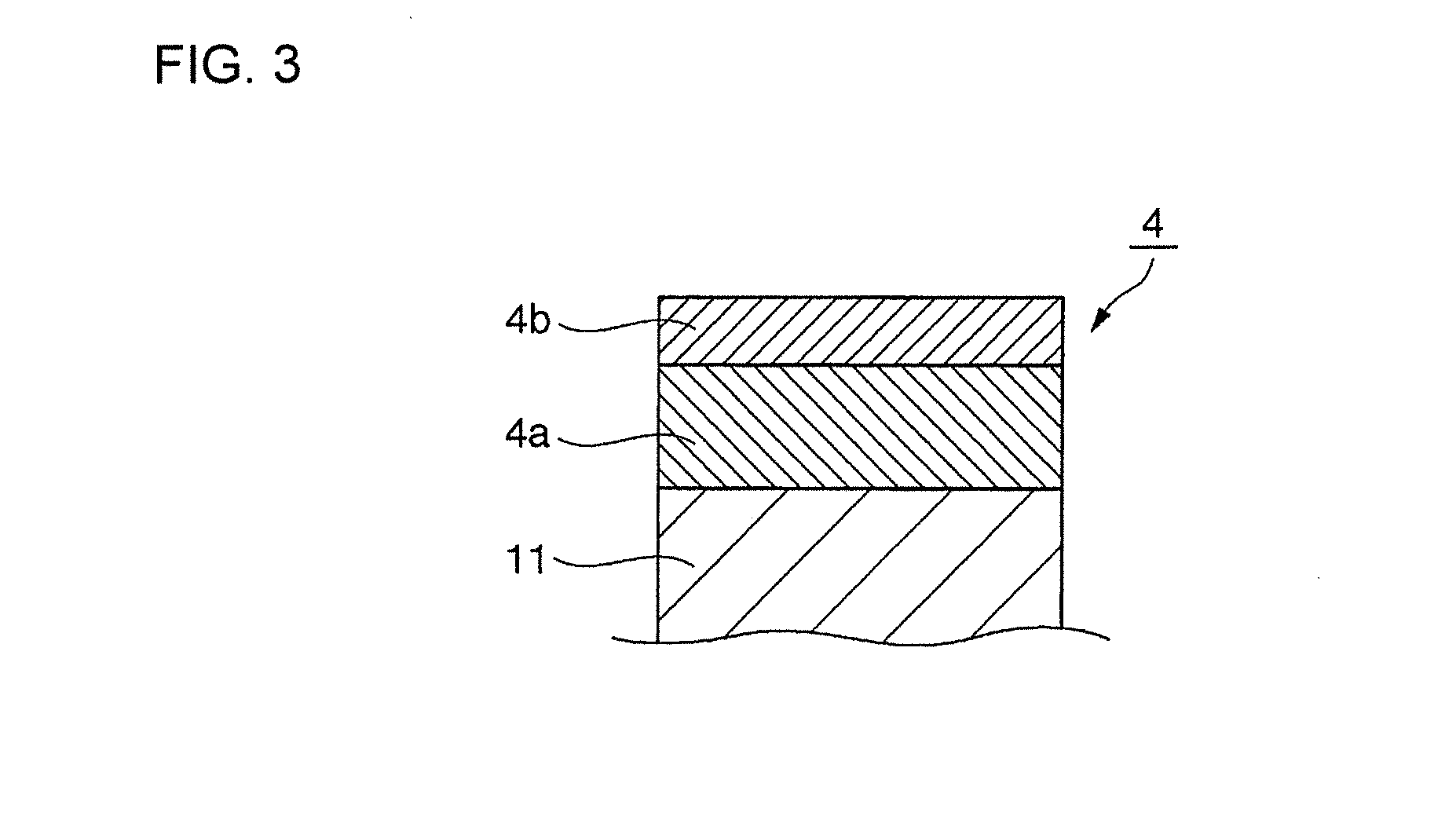
[0022]Steel pipe materials having an outer diameter of 8 mm and an inner diameter of 5 mm (Test material Nos. 1 to 9) were used as pipe base materials, and a Ni-plated layer (a layer thickness was 10 μm or more and 25 μm or less) composed of a diffusion layer having a layer thickness of 0.6 to 19.6 μm and a non-diffusion layer having a layer thickness of 3.1 to 20.6 μm was formed on an inner surface of each pipe by conventional electroplating and thermal treatment.

[0023]A result obtained by performing measurement of layer thicknesses of the Ni-plated layers composed of the diffusion layer and the non-diffusion layer and formed on steel pipe materials in the examples, corrosiveness test and followability test (bending working test) thereof in the following procedure is shown in Table 1.

Measurement of Layer Thickness of Ni-Plated Layer:

[0024]The layer thickness of the Ni-plated layer composed of the diffusion layer and the non-diffusion layer was measured by linear analysis using a sc...

example 1

Conventional Example 1

[0029]A result obtained by using a steel pipe material having an outer diameter of 8 mm and an inner diameter of 5 mm similarly to those of examples 1 to 9, forming only a non-diffusion layer having layer thickness of 7.0 μm on an inner surface of the pipe by conventional electroplating (without a non-diffusion layer), and performing a corrosiveness test and followability test (bending working test) in the same method as those of the above-described examples is also shown in Table 1. Measurement of the layer thickness of the Ni-plated layer was performed by the same method as those of the above-described examples 1 to 9.


PUM


Abstract

Provided is a steel fuel conveying pipe with high quality which has high resistance to corrosive fuel and followability, and allows working after plating. The steel fuel conveying pipe is characterized in that a Ni-plate layer is formed on an inner surface of a steel pipe of base material, the Ni-plated layer is wholly composed of a mutual diffusion layer including the base material and Ni and a non-mutual diffusion layer including only Ni formed on an outermost surface of the diffusion layer, a layer thickness of the non-mutual diffusion layer is 3 μm or more, and a total layer thickness of the mutual diffusion layer and the non-mutual diffusion layer is 10 μm or more and 25 μm or less.

Description

BACKGROUND[0001]1. Field of the Invention[0002]The present invention relates to a pipe for supplying fuel to an engine in a gasoline direct-injection engine system or a diesel engine system, and in particular to a pipe having resistance to inferior fuel containing a corrosive component.[0003]2. Description of the Related Art[0004]In recent years, in a gasoline direct-injection engine system whose development has been advanced in an automobile industry for the purpose of reducing environmental load according to fuel consumption improvement a pipe for supplying fuel (gasoline) to a direct-injection rail of an engine from a fuel tank via a pump has been demanded to have pressure resistance and air tightness higher than those of an existing multi point injection engine (see Japanese Patent Application Laid-Open No. 2006-152852). Further, in a diesel engine system, a fuel injection apparatus having a configuration where an injector has been coupled to each cylinder of a high-pressure fue...

Claims


Application Information

Patent Timeline
IPC IPC(8): F02M55/02F16L9/02
CPCF02M55/02F02M55/005F02M2200/9076F02M2200/05F02M2200/9053F16L9/02F16L19/028F02M2200/9046F02M2200/9038F02M55/004F02M2200/16F16L19/0243F16L58/08
Inventor KATSUMATA, AKI
Owner USUI KOKUSAI SANGYO KAISHA LTD
Why Eureka
Try Eureka