
In-band communication channel in optical networks

a technology of optical network and communication channel, applied in the field of optical communication system and method, can solve the problems of consuming valuable client/customer transport bandwidth, consuming gcc data rate in otn, and sdn hubbed nature, etc., and achieves the effect of less capacity, greater capacity, and greater capacity

Active Publication Date: 2016-08-11
CIENA
View PDF2 Cites 11 Cited by
  • Summary
  • Abstract
  • Description
  • Claims
  • Application Information

AI Technical Summary

Benefits of technology

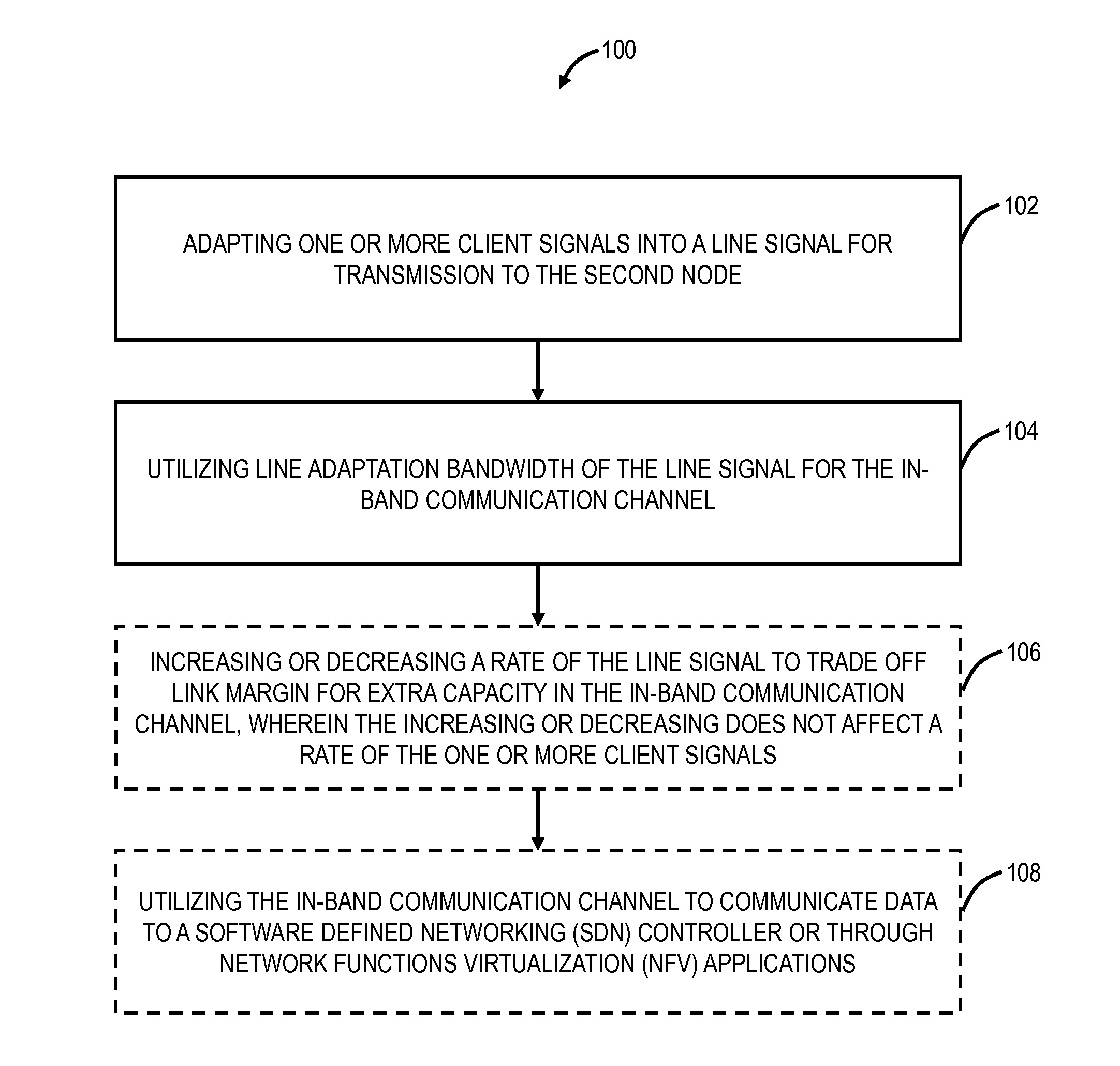
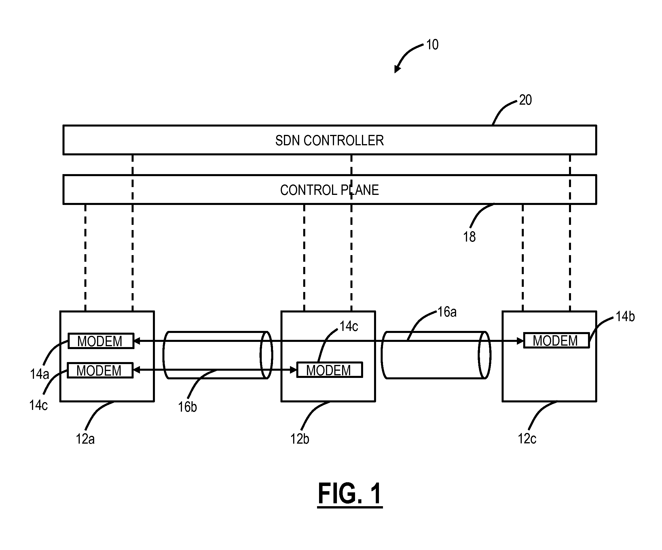
This patent describes a method and apparatus for providing an in-band communication channel in an optical network. The method involves adapting one or more client signals into a line signal for transmission to another modem, and utilizing the line adaptation bandwidth for the in-band communication channel. This allows for independent operation of the in-band communication channel and the client signals, and can be used for control plane signaling. The in-band communication channel can be at least an order of magnitude greater in capacity than the client signals. The apparatus includes optical modems and a controller for enabling communications between the in-band communication channels.

Problems solved by technology

The conventional GCC data rate in OTN will have difficulty in handling the hubbed nature of SDN and the evolving bandwidth requirements, in addition to control plane signaling, OAM & P data communication, etc.
Unattractive options include: 1) the OTN frame could be modified to allow for a higher rate OTN / GCC communication channel, but this is difficult due to standardization; 2) the line frame format (proprietary to each system vendor) could be designed to include a communications channel time slot meaning a higher required line rate, with the requisite required extra link margin; or 3) a dedicated SDN communication channel could be allocated in the client payload, but would consume valuable client / customer transport bandwidth, and such an approach has generally been commercially unacceptable at the transport layer.

Method used


Image

  • In-band communication channel in optical networks
  • In-band communication channel in optical networks
  • In-band communication channel in optical networks

Examples


Embodiment Construction

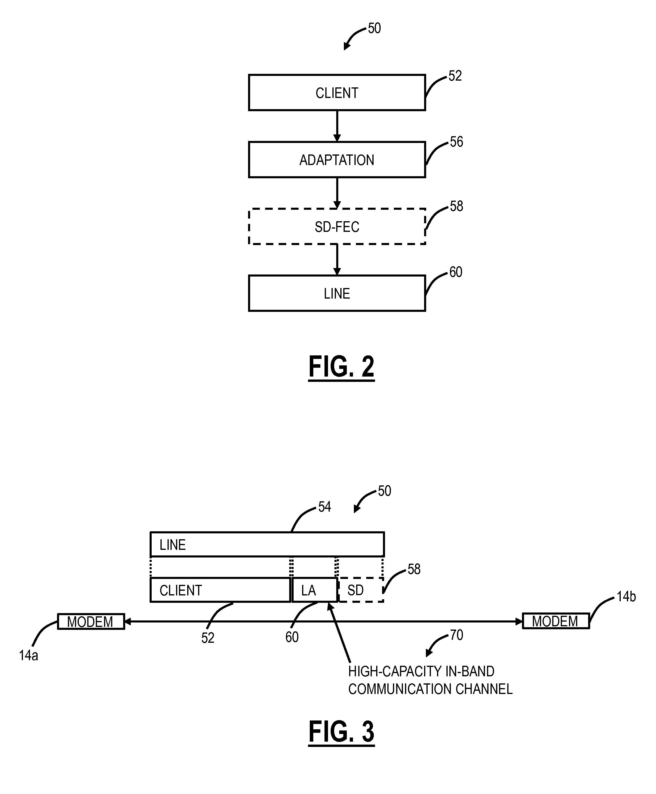
[0017]In various exemplary embodiments, an in-band communication channel, with higher capacity than existing in-band communication channels, is formed between two optical modems using line adaptation bandwidth. The line adaptation bandwidth is the difference between client bandwidth and line bandwidth. The client bandwidth can be rates based on Optical channel Transport Unit-k (OTUk) where k=2, 3, or 4; Optical channel Transport Unit Cn where C means 100 and n is a multiplier of 100, e.g. OTUC2 is ˜200 Gb / s, OTUC4 is ˜400 Gb / s, etc.; or the like. The line bandwidth can be based on a rate associated with a modem for a proprietary line side (Single Vendor Intra-Domain Interface (SV-IaDI)) and can vary based on baud-rate, modulation format, Soft-Decision Forward Error Correction (SD-FEC), and the like. The line rate adaptation bandwidth previously was idle or null data. Note, as described herein, the line adaptation bandwidth can be described as the difference between the actual client...


PUM


Abstract

Systems and methods, for an in-band communication channel in an optical network, include adapting one or more client signals into a line signal for transmission to the second node, and utilizing line adaptation bandwidth of the line signal for the in-band communication channel. The in-band communication channel is operationally independent from the one or more client signals while concurrently being transported together over the line signal. The line adaptation allows a rate of the line signal to be independent of rates of the one or more client signals.

Description

FIELD OF THE DISCLOSURE[0001]The present disclosure relates generally to optical communication systems and methods. More particularly, the present disclosure relates to a in-band communication channel in optical networks that may be used for Software Defined Networking (SDN) applications or the like.BACKGROUND OF THE DISCLOSURE[0002]Conventionally, optical networks rely on in-band communication channels for a variety of Operations, Administration, Maintenance, and Provisioning (OAM & P) functions as well as for control plane signaling and the like. Exemplary in-band communication channels include the Data Communication Channel (DCC) in Synchronous Optical Network (SONET) and Synchronous Digital Hierarchy (SDH) and the General Communication Channel (GCC) in Optical Transport Network (OTN). In contrast to SONET / SDH where the DCC has a constant data rate on the order of 1 Mb / s, the GCC data rate depends on the OTN line rate, i.e., Optical channel Data Unit (ODU) data rate. For example,...

Claims


Application Information

Patent Timeline
Patent Type & Authority Applications(United States)
IPC IPC(8): H04Q11/00H04L12/911H04J3/16
CPCH04Q11/0066H04Q2011/0086H04L47/828H04J3/1652
Inventor CLARKE, STEVENGAREAU, SEBASTIEN
Owner CIENA
Learn More