Dynamic Additive Manufacturing System

a manufacturing system and additive technology, applied in the direction of additive manufacturing processes, manufacturing tools, controlling lamination, etc., can solve the problems of unnecessarily limited system, limiting the accuracy of the end, and fabricated items that are less than optimal, so as to improve the quality of fabricated items, and facilitate the effect of movemen

Active Publication Date: 2016-08-18
KANAWHA AUTOMATION
View PDF2 Cites 55 Cited by
  • Summary
  • Abstract
  • Description
  • Claims
  • Application Information

AI Technical Summary

Benefits of technology

[0009]Yet other goals of embodiments of the invention include abilities to speed up fabrication processing through better movement, more seamless changes, and even by more optimal variations in activity to move to manufacturing the next layer or stage of the item to be fabricated. Embodiments can allow for varying layer repositioning according to calculated optimization for the stage of the item that has been fabricated or otherwise just for better speed. In some embodiments, variations in layer repositioning can be altered stereolithographic additive manufacturing processes and system and even for bottom-up photosolidification activities as use in additive manufacturing and the like. In

Problems solved by technology

In the area of additive manufacturing, however, systems have often been unnecessarily limited by aspects such as the way in which the actual additive manufacturing is physically achieved, and often the singular process capability presented by a particular 3D printer or the like.
This type of movement can at times limit the accuracy of the end result and make the fabricated item less than optimal.
Accordingly, better movement to achieve a better end resulting fabricated item have been desired, however, the limits of what was perceived as mandated stepper motor motions in an X and Y direction have been viewed as limited the possibilities for most additive manufacturing systems.
Such systems had little flexibility in accommodating other processing elements or other additive layup materials.
For example, for typical ink printers, as shown in U.S. Pat. No. 8,807,721, a cartridge is shown with replacement possible

Method used


Image

  • Dynamic Additive Manufacturing System
  • Dynamic Additive Manufacturing System
  • Dynamic Additive Manufacturing System

Examples


Embodiment Construction

[0021]As mentioned, the invention may be carried out in a wide variety of ways, and the examples discussed herein are simply that—examples. The present invention includes a variety of aspects, which may be combined in different ways. As such the following descriptions are provided to list elements and describe some of the embodiments of the present invention. These elements are listed with initial embodiments, however it should be understood that they may be combined in any manner and in any number to create additional embodiments. The variously described examples and preferred embodiments should not be construed to limit the present invention to only the explicitly described systems, techniques, and applications. Further, this description should be understood to support and encompass descriptions and claims of all the various embodiments, systems, techniques, methods, devices, and applications with any number of the disclosed elements, with each element alone, and also with any and...


PUM

PropertyMeasurementUnit
Mechanical propertiesaaaaaaaaaa
Responsivityaaaaaaaaaa
Timeaaaaaaaaaa

Abstract

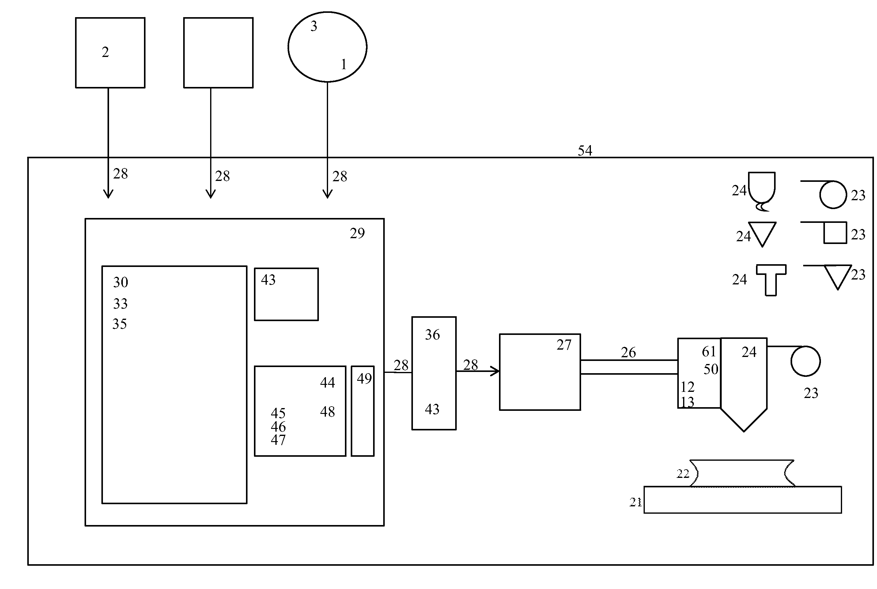
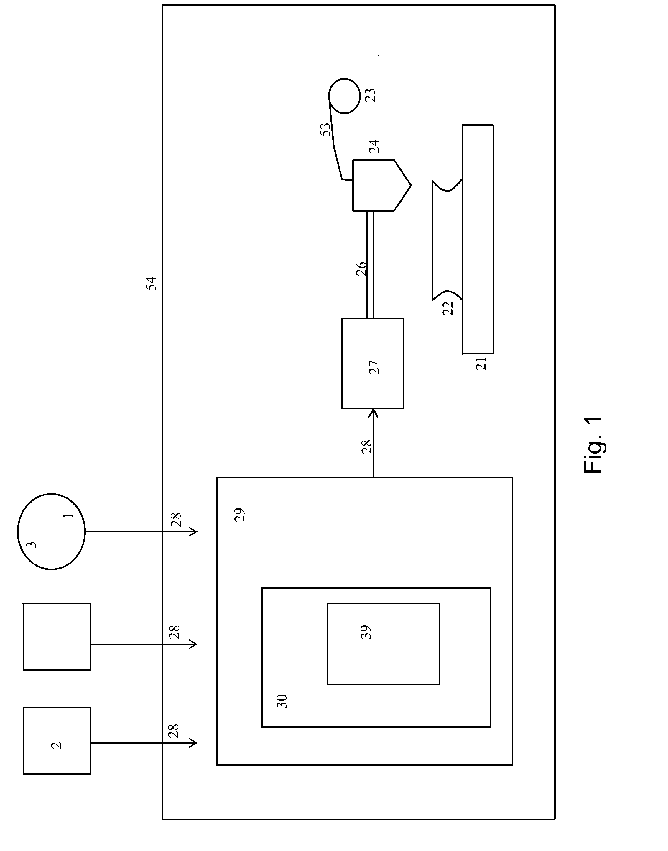
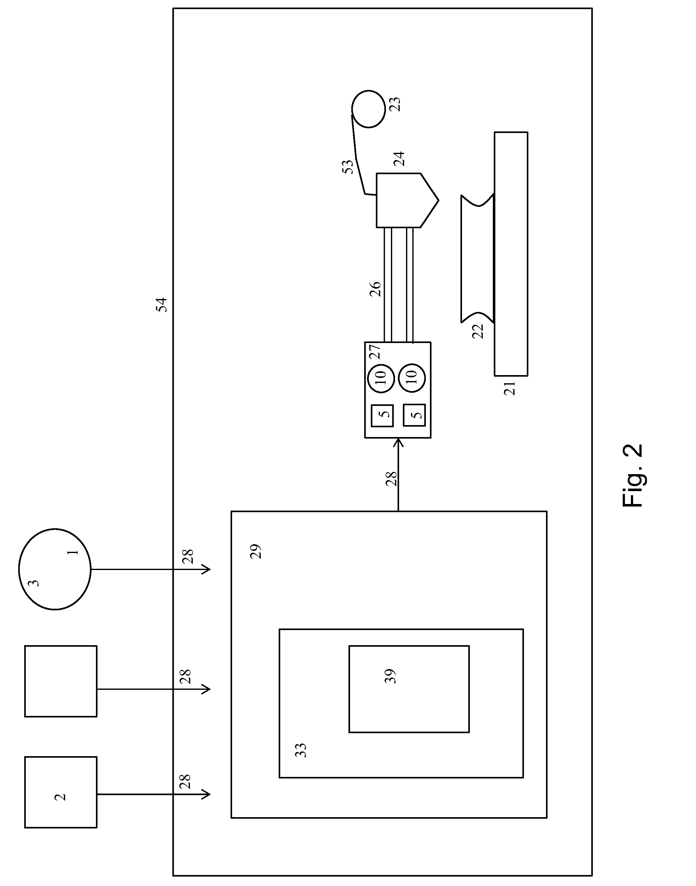
A dynamic manufacturing system such as for the additive manufacture of a fabrication item with multiformative capabilities presents a processor (29) that can refine movement, instructions, or data to achieve greater manufacturing efficiency and substantially uninterruptive change between formative process elements (24) or capabilities with simple user input (28) or indications. Optimization of movements, deposition of material, positioning, variant repositioning for next item layers during fabrication are provided in manners where the functions can be self contained such as in a 3D printer or the like and can be accomplished without significant interruptions to traditional processing times or even in shorter times through the improved transformations.

Description

TECHNICAL FIELD[0001]This invention relates to additive manufacturing systems and the like, including devices such as are commonly referred to as 3D printers. It especially relates to manufacturing systems that can be made dynamic and can present differing capabilities, can improve processes, and can provide better manufactured items. It especially relates to manufacturing systems that utilize dedicated, specialized processors for more efficient manufacturing, including both abilities to rapidly switch between formative capabilities without interruption and abilities to provide a more refined fabricated item.BACKGROUND[0002]Previous manufacturing systems have provided a number of features. In the area of additive manufacturing, however, systems have often been unnecessarily limited by aspects such as the way in which the actual additive manufacturing is physically achieved, and often the singular process capability presented by a particular 3D printer or the like. By design additive...

Claims


Application Information

Patent Timeline
IPC IPC(8): B29C67/00
CPCB32B41/00B29C67/0055B29K2105/0067B29C67/0088B29K2105/251B29C67/0074B29C67/0062B33Y50/02B33Y30/00B29C67/0085B29C64/106B29C64/118B29C64/124B29C64/141B29C64/147B29C64/232B29C64/393
Inventor GRIFFIN, ERICBUCKLEY, CHARLES
Owner KANAWHA AUTOMATION
Why Eureka
Try Eureka