
Systems and methods for controlling an inlet air temperature of an intercooled gas turbine engine

Inactive Publication Date: 2016-08-18
GENERAL ELECTRIC CO
View PDF52 Cites 11 Cited by
  • Summary
  • Abstract
  • Description
  • Claims
  • Application Information

AI Technical Summary

Benefits of technology

The present application and patent provide an intercooled gas turbine engine with a low pressure compressor, intercooler, high pressure compressor, second air line, bypass air line, and combustor. The engine also includes a high pressure turbine. The patent also describes a method to control the temperature of air supplied to the engine. The technical effects of the invention include improved engine efficiency, reduced emissions, and increased power output.

Problems solved by technology

However, when the ambient temperature is relatively high, the core engine temperature may reach an unacceptably high level if a high SHP is being delivered.
Some intercooled gas turbine engines may not include any means for controlling the temperature of the cooled air, and thus a certain variation in the cooled air temperature may be inevitable as the ambient temperature changes.
Although this indirect control method may be effective in some applications, it presents certain undesirable drawbacks.
Additionally, the amount of recirculation required for fast start-up may increase the cost of the intercooler system.
Furthermore, indirectly controlling the cooled air temperature by manipulating the cooling fluid entry temperature is an inherently slow control method due to the lag time between cooled air temperature measurement, cooling fluid temperature change, intercooler equilibrium, and cooled air temperature change.

Method used


Image

  • Systems and methods for controlling an inlet air temperature of an intercooled gas turbine engine
  • Systems and methods for controlling an inlet air temperature of an intercooled gas turbine engine
  • Systems and methods for controlling an inlet air temperature of an intercooled gas turbine engine

Examples


Embodiment Construction

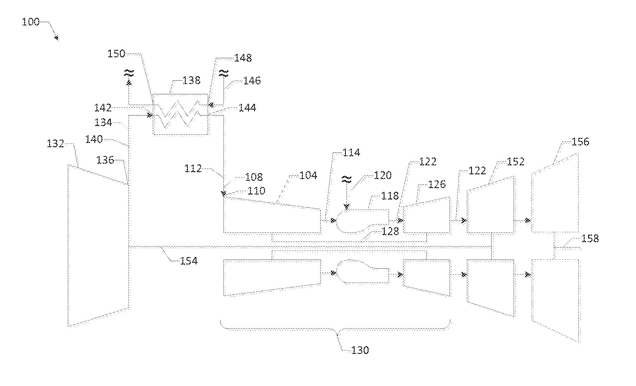
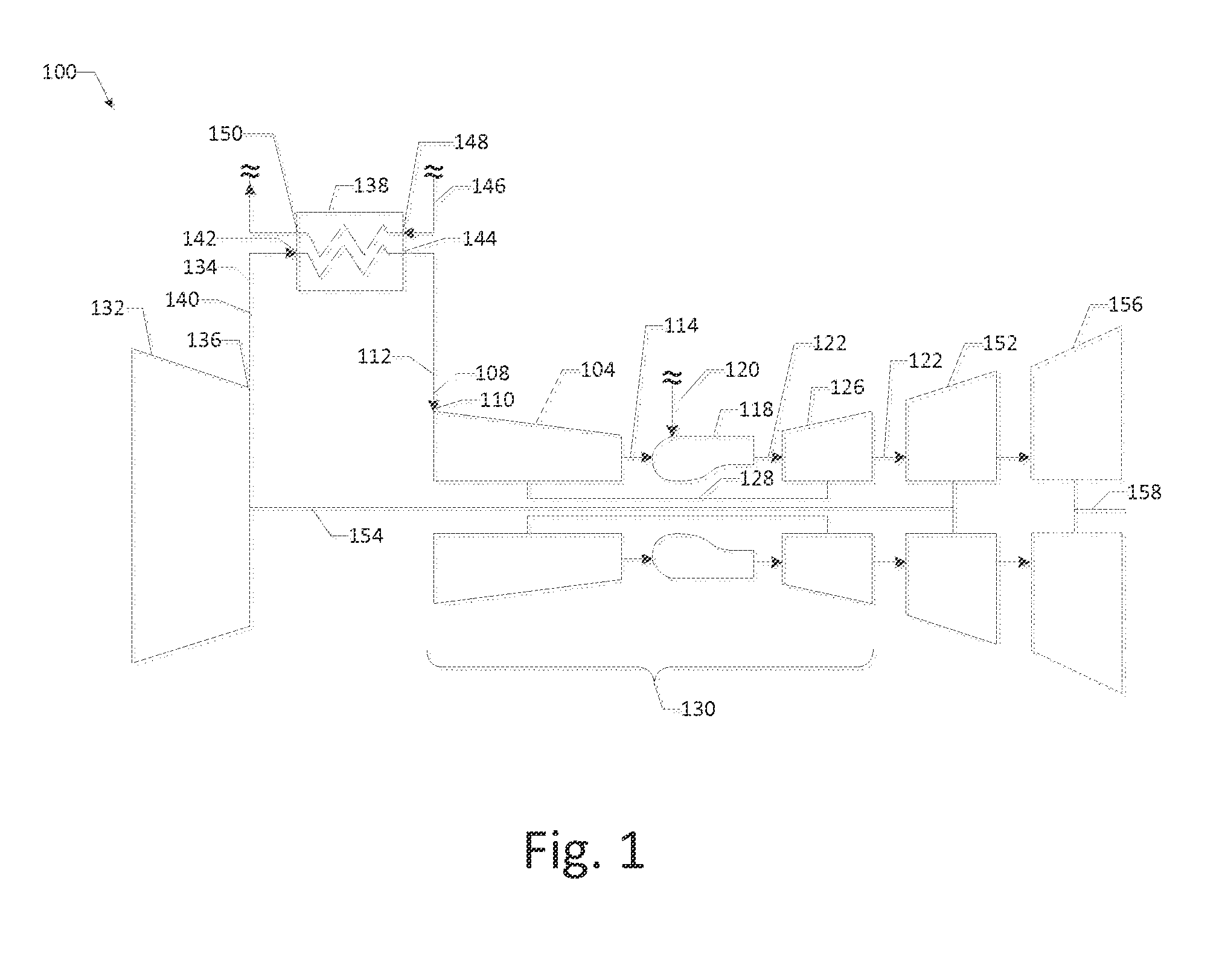
[0013]Referring now to the drawings, in which like numerals refer to like elements throughout the several views, FIG. 1 shows a schematic diagram of a known gas turbine engine 100. The gas turbine engine 100 may include a high pressure compressor 104 for compressing an incoming flow of air 108 received via an air inlet 110 of the high pressure compressor 104. The incoming flow of air 108 may be supplied to the high pressure compressor 104 via an air inlet line 112 extending to the air inlet 110. The high pressure compressor 104 produces a compressed flow of air 114 (at a high pressure), which may be delivered to a combustor 118 of the gas turbine engine 100. The combustor 118 mixes the compressed flow of air 114 with a pressurized flow of fuel 120 and ignites the mixture to create a flow of combustion gases 122. Although only a single combustor 118 is shown, the gas turbine engine 100 may include any number of combustors 118, which may be arranged in an annular array about a longitu...


PUM


Abstract

The present application and the resultant patent provide an intercooled gas turbine engine. The intercooled gas turbine engine may include a low pressure compressor configured to produce a compressed flow of air, an intercooler, a low pressure compressor configured to produce a compressed flow of air, a high pressure compressor, a second air line positioned between the intercooler and the high pressure compressor and configured to direct the first portion of the compressed flow of air toward the high pressure compressor, and a bypass air line positioned between the low pressure compressor and the high pressure compressor and configured to direct a second portion of the compressed flow of air to the second air line. A related method of controlling a temperature of an incoming flow of air supplied to a core engine of an intercooled gas turbine engine also is provided.

Description

TECHNICAL FIELD[0001]The present application and the resultant patent relate generally to gas turbine engines and more particularly relate to systems and methods for controlling an inlet air temperature of an intercooled gas turbine engine.BACKGROUND OF THE INVENTION[0002]Generally, an intercooled gas turbine engine may include a high pressure compressor for compressing an incoming flow of air, a combustor for mixing the compressed flow of air with a pressurized flow of fuel and igniting the mixture to create a flow of combustion gases, and a high pressure turbine for producing mechanical work as the flow of combustion gases passes therethrough. The high pressure compressor, the combustor, and the high pressure turbine may collectively be referred to as the “core engine.” In some applications, an intercooled gas turbine engine also may include a low pressure compressor, which alternatively may be referred to as a “booster,” for supplying compressed air to the high pressure compresso...

Claims


Application Information

Patent Timeline
IPC IPC(8): F02C7/18F02C3/04
CPCF05D2260/211F02C7/143F02C7/18F04D29/5826F02C3/04F02C9/18F04D19/026F05D2270/303
Inventor SCARBORO, PAUL ROBERTSHARRIS, JOSEPH
Owner GENERAL ELECTRIC CO
Features
  • Generate Ideas
  • Intellectual Property
  • Life Sciences
  • Materials
  • Tech Scout
  • Unparalleled Data Quality
  • Higher Quality Content
  • 60% Fewer Hallucinations
Learn More