Light Emitting Diode (LED) Dimmer Circuit and Dimming Method for LEDs

a technology of leds and dimming circuits, which is applied in the direction of lighting apparatus, electrical equipment, light sources, etc., can solve the problems of increased system cost &/or resolution loss, easy flicker of led lighting, and inability to meet the needs of lighting, etc., to achieve high dimming ratios without loss of linearity, eliminate the need and requirements, and eliminate the effect of need and requirements

Active Publication Date: 2016-08-18
GLOBALFOUNDRIES US INC
View PDF0 Cites 15 Cited by
  • Summary
  • Abstract
  • Description
  • Claims
  • Application Information

AI Technical Summary

Benefits of technology

[0014]In one aspect of the invention a dimming method and a dimmer circuit for LED lighting, to obtain flicker free dimming without compromising linearity and resolution, and for obtaining any desired dimming profile is presented. The dimmer circuit includes an appropriate front end module that can be either an analog module, a digital module, a software module based on the lighting application. The dimmer circuit includes a firmware module, that interacts with the analog module, a digital module, a software module via an event generator. The analog module, the digital module and the software module generate one or more events that corresponds to an external dimming input, through the event based module, and a response to process the one or more events (either in analog, digital or software domain) is determined by the firmware module.

Problems solved by technology

LED systems have their own requirements and limitations such as LED lighting is susceptible to flicker, thermal runaway issues and various fault scenarios and requires more precise current and heat management.
a. Any minimal change in intensity is easily perceived by eye
b. A quick (step) change in intensity appears as a flash
c. A noise in external dimming signal manifests as rapid change in light intensity and appears as flicker
d. To overcome this noisy external signal, certain system filtering techniques & components are implemented to eliminate the noise. However this results in added system cost &/or loss in resolution
e. There is a loss of linearity in average currents at deep dimming ratios
Due to these challenges, it is very difficult to achieve smooth, no resolution loss and linear dimming using the current dimming techniques and circuits.
Nonetheless, noise on analog dimming signal has a bearing on quality of output light.
Both these approaches have certain limitations due to real world system complexity.
a. The throttling of LED currents back and forth can appear as a sudden drop in light intensity or a flash.
b. Throttling of LED currents by modulating the peak currents, (i.e.) Analog dimming, results in shift in color compensation.
This is diffi

Method used


Image

  • Light Emitting Diode (LED) Dimmer Circuit and Dimming Method for LEDs
  • Light Emitting Diode (LED) Dimmer Circuit and Dimming Method for LEDs
  • Light Emitting Diode (LED) Dimmer Circuit and Dimming Method for LEDs

Examples


Embodiment Construction

[0026]As used herein and in the claims, the singular forms “a,”“an,” and “the” include the plural reference unless the context clearly indicates otherwise.

[0027]As used herein, the term “LED” means light emitting diodes which is a semiconductor light source capable of emitting different colored light intensity such as but not limited to red, visible, ultraviolet, infra-red wavelengths.

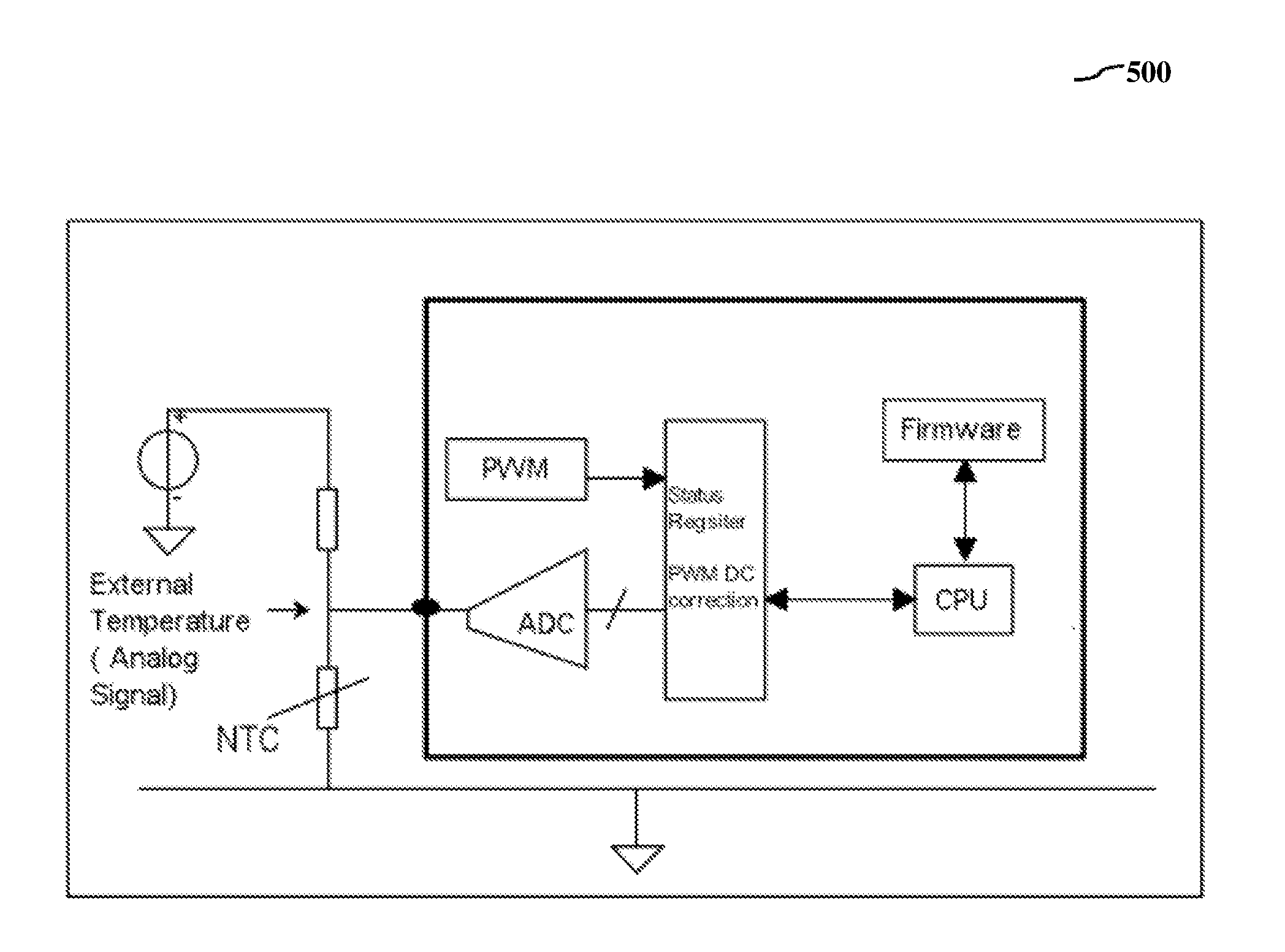
[0028]As used herein, the term “LED circuit” or “LED driver system” is an electric power circuit used for powering an LED.

[0029]As used herein, the term “LED dimmer circuit” or “dimmer circuit” is an electric power circuit used for dimming operation for an LED. In specific implementation the LED driver system and LED dimmer circuit are integrated into one circuitry.

[0030]As used herein, the term “firmware” means embedded software and computer programs and instructions or code, memory and data stored in it. Specifically in relation to the invention firmware has control and operating instructions for all...


PUM


Abstract

A dimmer circuit (100) and a dimming method for an event based integrated driver system for a light emitting diode lighting application is disclosed. Dimmer circuit (100) includes a front end module for receiving an external dimming input in an analog domain, a digital domain or software domain and for operating a dimming output; an event generator for generating a plurality of events in a prioritized manner to trigger a respective response through front end module; and a firmware module configured for storing instructions for processing the plurality of events in the prioritized manner and for processing each response to implement a functionality in dimming output, where front end module, event generator and firmware module communicate with each other to generate dimming output of the one or more LEDs, and the dimming output has at least one of a linear profile, a non linear profile, a custom profile or combinations thereof.

Description

[0001]This application takes priority from the Provisional application 4409 / CHE / 2013 filed with the Indian Patent Office on 27 Sep. 2013.FIELD OF THE INVENTION AND USE OF INVENTION[0002]The invention relates generally to light emitting diodes (LED) and more specifically to a dimmer circuit incorporated in a driver system for LEDs and associated dimming methods, useful in achieving flicker free dimming without compromising linearity and resolution of the LED lighting.PRIOR ART AND PROBLEM TO BE SOLVED[0003]LEDs are used in a variety of applications as indicator lamps and in different types of lighting environments, for example in aviation lighting, digital microscopes, automotive lighting, backlighting, advertising, general lighting, and traffic signals. Customized lighting solutions using LEDs are also being desired by the consumers.[0004]Typically, the LED driver circuit is incorporated in an IC (referred herein as driver IC) and is a constant current source that drives the LEDs to...

Claims


Application Information

Patent Timeline
IPC IPC(8): H05B33/08H05B44/00
CPCH05B33/0815H05B33/0854H05B33/0821H05B33/0845H05B45/10H05B45/37
Inventor BHAGWAT, HRISHIKESHBHAGWAT, KRISHNADASSWAMINATHAN, RAJESHSAMANTHA, SOMNATHKHARE, ABHISEK
Owner GLOBALFOUNDRIES US INC
Why Eureka
Try Eureka