
System for the detection and classification of buried unexploded ordnance

a technology for detecting and identifying unexploded objects, applied in the field of system for detecting unexploded ordnance, can solve the problems of inability to distinguish between uxo and non-hazardous items in current technology, large problem of uxo contamination at former and current dod sites, and high cost of implementation, so as to reduce the number of anomalies, improve spatial resolution, and mitigate the problem of data processing/analysis

Active Publication Date: 2016-08-25
UNITED STATES OF AMERICA
View PDF21 Cites 3 Cited by
  • Summary
  • Abstract
  • Description
  • Claims
  • Application Information

AI Technical Summary

Benefits of technology

The patent describes a new system that can detect and classify unusual objects, including in difficult terrain and treed areas. The system can operate in both a dynamic, or survey mode for anomaly detection or a cued mode for more targeted data collection. The system uses small sensors, which make it easier to process and analyze data. The results show that the system can detect and classify objects with a high level of accuracy, potentially reducing the need for additional data collection. Overall, the invention provides an effective tool for detecting and classifying 16 anomalies per acre per day.

Problems solved by technology

UXO contamination at former and current Department of Defense (DOD) sites is an extensive problem.
Site characterization and remediation activities conducted with the current state-of-the-art technologies at these sites often yield unsatisfactory results and are extremely expensive to implement.
This is due in part to the inability of current technology to distinguish between UXO and nonhazardous items.
The system also has undesirably large sensor dimensions, and suffers from signal response drift due to its analog electronic design.
In survey mode, it can only provide detection because the single transmitter only allows for the collection of a limited data set.

Method used


Image

  • System for the detection and classification of buried unexploded ordnance
  • System for the detection and classification of buried unexploded ordnance
  • System for the detection and classification of buried unexploded ordnance

Examples


Embodiment Construction

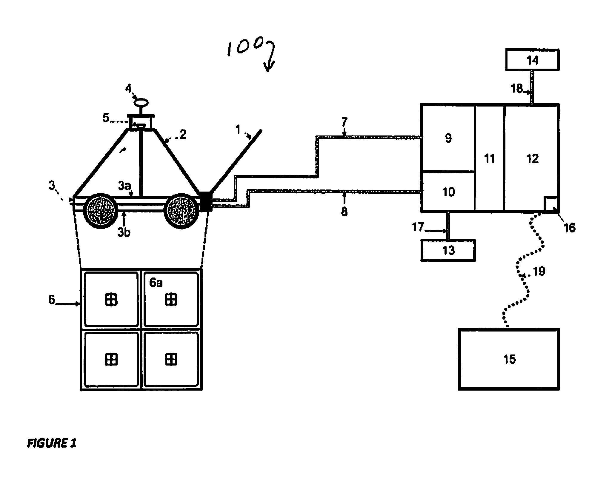
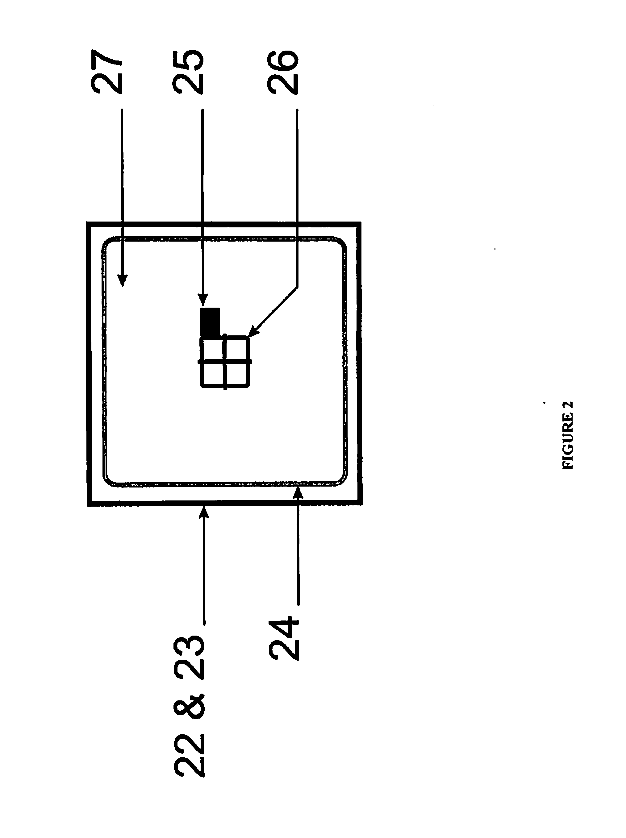
[0016]Referring now to FIG. 1, system 100 includes a wheeled cart 1 (with a handle for pushing by an operator) mounted on which is a GPS (global positioning system) / IMU (inertial measurement unit) tripod 2 and a sensor bed 3 comprising an upper sensor shell 3a and a lower shell 3b. Positioned on tripod 2 are a GPS antenna and receiver for providing the location of the cart 4 (e.g. latitude, longitude, and elevation) and an IMU 5 for providing the orientation of the cart (e.g. Pitch, Roll, and Yaw). A sensor array 6 is sandwiched in between the two parts of the sensor bed 3 and includes TEMTADS / 3D sensor 6a. A receiver cable 7 is attached at a first end to each receiver part of sensor 6a of sensor array 6 and at a second end to a receiver electronics 9. A transmitter cable 8 is attached at a first end to each transmitter portion of sensor 6a of sensor array 6 and at a second end to a transmitter electronics 10. Data acquisition electronics 11 acquires the received data and inputs the...


PUM


Abstract

A sensor system for detecting buried metal objects such as unexploded ordnance and the collection of data for the classification of the detected objects based on parameters extracted from the collected data includes a wheeled cart, positioned on which is an array of transmitter coils for transmitting a series of excitation signals onto the area of interest and a sensor array of receiver coils and preamplifiers for receiving back the resultant eddy current decays emitted by the buried objects, a computer, and data acquisition electronics for acquiring and storing the received decays as decay data within the computer. The incoming EMI data are digitized and a data fitting process is performed to extract fit location and shape parameters. These data can be transferred to other data analysis systems for comparison to previously recorded signatures to determine whether the received decay data from the area of interest is attributable to buried metal objects or conversely to an object constituting an anomaly.

Description

CROSS-REFERENCE TO RELATED APPLICATIONS[0001]This Application claims the benefit of U.S. Provisional Application 61 / 783,051 filed on Mar. 14, 2013, and incorporated herein by reference.FIELD OF THE INVENTION[0002]The invention is directed to a system for the detection of buried metal objects and the classification of the detected objects on the basis of shape parameters extracted from the modeling of the collected data, and more particularly to a system for distinguishing potentially hazardous buried unexploded ordnance (UXO) from non-hazardous scrap and range debris.BACKGROUND OF THE INVENTION[0003]UXO contamination at former and current Department of Defense (DOD) sites is an extensive problem. Site characterization and remediation activities conducted with the current state-of-the-art technologies at these sites often yield unsatisfactory results and are extremely expensive to implement. This is due in part to the inability of current technology to distinguish between UXO and non...

Claims


Application Information

Patent Timeline
Patent Type & Authority Applications(United States)
IPC IPC(8): F41H11/136G01V3/10
CPCG01V3/12G01V3/104F41H11/136G01V3/17
Inventor NELSON, HERBERT H.STEINHURST, DANIEL A.HARBAUGH, GLENN R.BELL, THOMAS H.
Owner UNITED STATES OF AMERICA
Learn More