Supercharge Your Innovation With Domain-Expert AI Agents!

Resonant unit, voltage controlled oscillator (VCO) implementing the same, and push-push oscillator implementing a pair of vcos

a voltage control and oscillator technology, applied in the field of resonance circuits, can solve the problems of difficult enhancement of q-value of micro-strip lines integrally formed on semiconductor materials, degraded phase noise of oscillators, and the inability to achieve techniques similar to those above described

Active Publication Date: 2016-08-25
SUMITOMO ELECTRIC IND LTD
View PDF2 Cites 3 Cited by
  • Summary
  • Abstract
  • Description
  • Claims
  • Application Information

AI Technical Summary

Benefits of technology

The present patent application is about a push-push oscillator that generates oscillation signals of even overtones of the fundamental oscillating frequency and eliminates oscillation signals of odd overtones. The push-push oscillator includes a pair of voltage controlled oscillators (VCOs) with resonant units and negative resistance units. The resonant units have impedance determining the fundamental oscillating frequency, while the negative resistance units have a transistor connected to the resonant transmission lines and an output port. The push-push oscillator generates oscillation signals with even overtones and eliminates odd overtones.

Problems solved by technology

However, such a resonant unit formed on the semiconductor material inevitably shows an inferior Q-value because of relatively smaller phase shift of micro-strip lines formed on the semiconductor material; accordingly, the phase noise of the oscillator becomes degraded.
A key factor is that the phase shift thus configured for a micro-strip line has restricted the Q-value of the oscillator, that is, the micro-strip line integrally formed on the semiconductor material is hard to enhance the Q-value.
However, in further higher frequencies such as those in millimeter wavelengths, techniques similar to those above described becomes almost impossible.

Method used


Image

  • Resonant unit, voltage controlled oscillator (VCO) implementing the same, and push-push oscillator implementing a pair of vcos
  • Resonant unit, voltage controlled oscillator (VCO) implementing the same, and push-push oscillator implementing a pair of vcos
  • Resonant unit, voltage controlled oscillator (VCO) implementing the same, and push-push oscillator implementing a pair of vcos

Examples


Embodiment Construction

[0020]Next, some embodiments according to the present invention will be described as referring to drawings. In the description of the drawings, numerals or symbols same with or similar to each other will refer to elements same with or similar to each other without duplicating explanations.

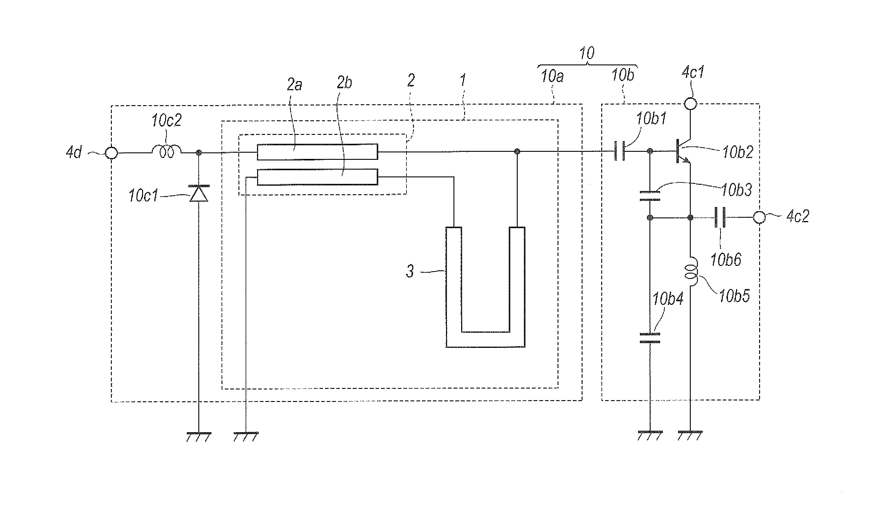
[0021]A resonant circuit 1 according to one embodiment of the present invention will be described as referring to FIG. 1. The resonant circuit 1 shown in FIG. 1, which has micro-strip lines showing relatively restricted signal loss of a type of a two-dimensional monolithic microwave integrated circuit (MMIC), is applicable to, for instance, a voltage controller oscillator (VCO). The resonant circuit 1 is formed on a primary surface of a substrate, which is omitted in the figures, made of, for instance, gallium arsenide (GaAs). The GaAs substrate may include the resonant circuit 1 within a dielectric film provided on a primary surface of the GaAs substrate, where the dielectric film may have a thick...


PUM


Abstract

A resonant circuit to be connected to a negative resistance unit is disclosed. The resonant circuit includes a pair of resonant transmission lines electrically coupled to each other and a coupling transmission line connecting the resonant transmission lines. The resonant transmission lines and the coupling transmission line are formed on a semiconductor substrate. The resonant transmission lines have a length corresponding to a quarter wavelength (λ / 4) of twice of the resonant frequency attributed to the resonant circuit.

Description

BACKGROUND OF THE INVENTION[0001]1. Field of the Invention[0002]The present application relates to a resonant circuit applicable to an oscillator.[0003]2. Background Arts[0004]Conventional communication systems usually implement a voltage controller oscillator (VCO), which includes a resonant unit and an amplifier, for generating an oscillating signal. The resonant unit often has a type of a micro-strip line because of relatively restricted signal loss and relatively high Q-value thereof, which are parameters showing steepness of the resonance, in order to reduce phase noises in frequency bands of a microwave and / or a millimeter wave.[0005]A Japanese Patent laid open No. 2008-141291A has disclosed techniques relating to microwave filters and high frequency oscillators. The microwave filters and the high frequency oscillators disclosed therein have an oscillator and the band-passing filter integrated on a quartz substrate, which inevitably has an excellent Q-value. As such, a resonan...

Claims


Application Information

Patent Timeline
Patent Type & Authority Applications(United States)
IPC IPC(8): H01P7/02H03B7/06H03J3/20
CPCH01P7/02H03B7/06H03J3/20H01P5/185H03B5/1847H03B5/1852H03B5/18H03B1/00H03L1/022H03L7/00H03L7/08H03L5/00H03L3/00H03L7/0891H03L7/06H03L7/18H03L7/10
Inventor KAWASAKI, TAKESHITOKUMITSU, TSUNEO
Owner SUMITOMO ELECTRIC IND LTD
Features
  • R&D
  • Intellectual Property
  • Life Sciences
  • Materials
  • Tech Scout
  • Unparalleled Data Quality
  • Higher Quality Content
  • 60% Fewer Hallucinations
Learn More