
Cathode cutting device using laser

Active Publication Date: 2016-09-15
LG ENERGY SOLUTION LTD
View PDF3 Cites 9 Cited by
  • Summary
  • Abstract
  • Description
  • Claims
  • Application Information

AI Technical Summary

Benefits of technology

The present invention provides a cathode cutting device that can cut cathodes of various shapes without stopping the manufacturing line, resulting in a high yield and operation rate. Additionally, the device can lower the cost of the cathode cutting process.

Problems solved by technology

As such, when an electrode material is cut by using the mold cutter, there is an advantage in that cutting quality is high but there are limitations in that it takes a lot of time to manufacture a mold cutter having a precise shape and the mold cutter itself is expensive, and there is another limitation in that it has no choice but to cut the electrode material according to the shape of the mold cutter only.
Providing and replacing various kinds of mold cutters do not only increase the production cost of the mold cutter but also remarkably decrease the yield of the electrode plate that may be produced for a unit time.

Method used


Image

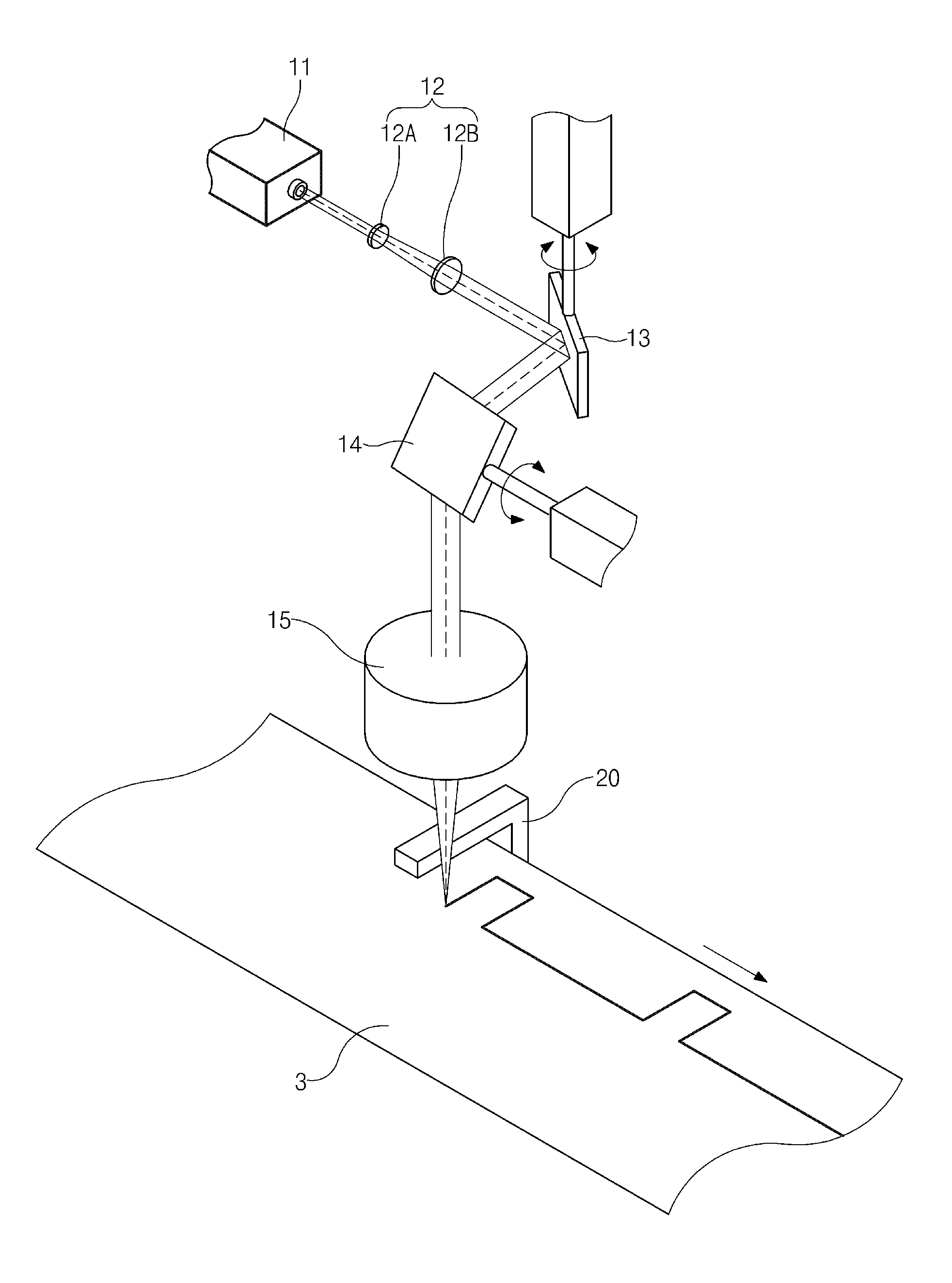
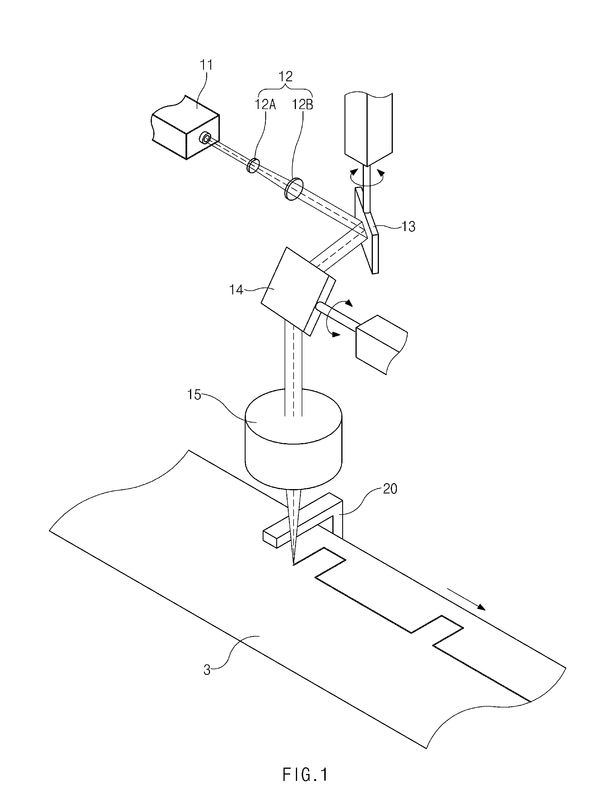
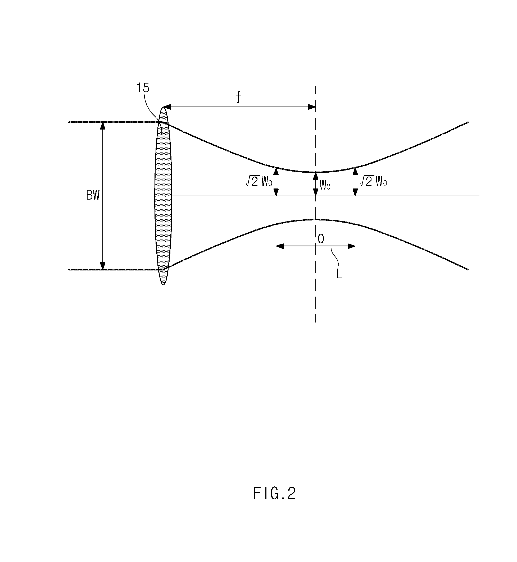
  • Cathode cutting device using laser
  • Cathode cutting device using laser
  • Cathode cutting device using laser

Examples


Embodiment Construction

[0033]In the following, an exemplary embodiment of the present invention is described in detail. However, the present invention is not limited or defined by the following embodiment.

[0034]The terms or words used in the detailed description and claims should not be limitatively construed as typical meanings or meanings indicated in dictionaries but should be construed as meanings and concepts matching the technical spirit of the present invention based on the principle that the inventor may properly define the concepts of terms in order to describe his or her invention in the best mode.

[0035]In the drawing, the size of each component or a specific part of the component is exaggerated, omitted or simply shown for the convenience and clarity of description. Thus, the size of each component does not substantially reflect an actual size. When it is determined that a detailed description of a related known function or configuration may unnecessarily obscure the subject of the present inve...


PUM

PropertyMeasurementUnit
Lengthaaaaaaaaaa
Lengthaaaaaaaaaa
Poweraaaaaaaaaa

Abstract

The present invention relates to a lithium secondary battery, and more specifically to a lithium secondary battery having a multi-directional lead-tab structure. The lithium secondary battery of the present invention includes: an electrode assembly which is formed by alternately laminating an electrode plate having a current collector, an active material, and a tab, and an isolation layer; a lead which is electrically connected to the tab; and a battery case, wherein the lead is divided into an anode lead and a cathode lead, and at least two or more anode leads and cathode leads are provided. The battery of the present invention uses the same lead-tab size as the prior art and is suitable for use with high current.

Description

CROSS-REFERENCE TO RELATED APPLICATIONS[0001]This application claims the priority of Korean Patent Application No. 10-2013-0132063 filed on Nov. 1, 2013, in the Korean Intellectual Property Office, the disclosure of which is incorporated herein by reference.TECHNICAL FIELD[0002]The present invention relates to a cathode cutting device using a laser and more particularly, to a cathode cutting device that may continuously cut a cathode sheet by using a laser.BACKGROUND ART[0003]In general, a demand for a secondary battery is increasing due to the technological development of a mobile device and an increase in demand therefor, and among others, a lithium (ion / polymer) secondary battery having a high energy density and operating voltage and excellent preservation and life characteristics is being widely used as an energy source for various electronic products including various mobile devices.[0004]The lithium (ion / polymer) secondary battery has a structure in which an electrode assembly...

Claims


Application Information

Patent Timeline
IPC IPC(8): B23K26/38B23K26/082B23K26/06B23K26/073B23K26/042B23K26/0622H01M4/04
CPCB23K26/38B23K26/042B23K26/082B23K26/0648B23K26/073B23K26/0622B23K26/0665B23K26/0846B23K2101/38B23K2101/16B23K26/083H01S3/10
Inventor KIM, TAE SUKI EUN, SUNGLEE, SANG IKLEE, JIN SOOBAN, JIN HOSEO, DAE HANSHIN, BU GONMIN, KI HONGYUK, YOUNG MINAHN, CHANG BUM
Owner LG ENERGY SOLUTION LTD
Learn More